Got a big question...............What kind of monster speaker(s) will you use on this beast of an amp? 😱 

On my 350W unit, I've severely blown TWO 12 inch woofers, and now seriously considering a 15 instead! I could only imagine the damage 1000W could do!
1st generic 12" 350/700W kept breaking/melting the lead wires, repaired several times, and eventually the coil/cone assy got loose and the coil started rubbing the magnet. Cone got brittle too.
2nd 12" was a Sony P5W. 350/1200W It seemed to take everything I could throw at it, until one day, after 4 minutes of playing Black Sabbath's "War Pigs" at full volume, sparks lit up behind the speaker cone, blew my fuse, and the coil and shorting ring melted together as one and reads 0.9 ohms now.
I wish you luck with 1000W!
On my 350W unit, I've severely blown TWO 12 inch woofers, and now seriously considering a 15 instead! I could only imagine the damage 1000W could do!
1st generic 12" 350/700W kept breaking/melting the lead wires, repaired several times, and eventually the coil/cone assy got loose and the coil started rubbing the magnet. Cone got brittle too.
2nd 12" was a Sony P5W. 350/1200W It seemed to take everything I could throw at it, until one day, after 4 minutes of playing Black Sabbath's "War Pigs" at full volume, sparks lit up behind the speaker cone, blew my fuse, and the coil and shorting ring melted together as one
and reads 0.9 ohms now.I wish you luck with 1000W!
MJL21193 said:
Yes, this is what I had in mind. Pretty much a waste of a circuit board to mount that many devices.
What do you think of my idea to use the heatsinks as the rails? The more I consider it, the more I like it.
Thanks! I didn't know this. One of the hazards of being a rookie.
🙂
Here is what I would do. Star wire both supply and speaker, the only way to avoid problems.
Attachments
EWorkshop1708 said:Got a big question...............What kind of monster speaker(s) will you use on this beast of an amp? 😱
I wish you luck with 1000W!
It's important to keep in mind that the 1000 watts is the 2 ohm power and this amp will (initially) be used for an existing 4 ohm speaker (therefore JUST 500 watts). The future holds many wondrous things though...
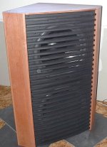
The sub I have now is pictured below. It has two 18" drivers (mj-18 from Mach 5 Audio). These were very cheap but well suited for this application - a sealed LT EQ'ed sub. The internal volume of the cabinet is 100 litres and the idea was to drive the resonant peak up to ~80Hz, thereby giving a flat, easy load for the amp to drive below that (where the LT has the most boost).
This sub, properly driven, is THE most impressive audio thing I've ever made. The bass it produces is pure, with no hint of "boom".
This has been driven hard by me and was truly tested when my son (17 years old) had a few of his friends here when I wasn't around. They gave it a workout!
Attachments
I have seen that sub before but didn't realise those were 18" drivers 😱 , very well proportioned. If they are both 8 ohms they "only" need to handle 250W RMS each, which i'm sure they could. At least you can justify such a powerful build 😀
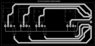
If you really want to mount a load of output devices, I would forego doing that on a PCB and borrow an idea from AmpsLab:

As you can see (if you look closely!) he's used solid copper wire suspended between two terminal blocks to provide the power, output and base wires. That would work far better than pcb.
If you really DO want to use PCB, then you could simply reinforce the power tracks with solder or copper wire bent into the right shape.
Hi,
What is the advantage of running Q5 & Q18 at under 3mA?
I would lower R4 & R45 to less than 100r maybe even 30r.
For home use that sink and ClassB is probably good enough.
I would bias it to full ClassAB (Vre=25mV) and use twice the heatsink for home use.
Smoothing @ +-20mF to +-40mF would be OK for 8ohm to 4ohm loading. If you envisage 2ohm loading then consider +-80mF to +-100mF, but you'll also need to reduce C6 to 150uF.
Using +-80mF you'll need about +-73Vdc to get your 1kW target. But reducing it to +-20mF needs the supply to be upped to about +-81Vdc when using a 4% regulation transformer of about 1.5kVA.
Alternatively,
build two amps each of around 500W into 4r0 (not 1000W into 2r0) and drive each speaker individually. You still get your 500W total into the box.
Re: Re: Re: Re: Re: 1000 Watt Sub Amp: Design / Build
Unfortunately, that's one good way to get broken leads. Works ok with TO-3, but not the MJLs. Think about a motherboard/daughterboard arrangement. The followers, Vbe stack, and emitter/base resistors aren't likely to change as the design evolves. The front end might.
New amp of mine in progress does just that. Heatsinks will be at rail voltage (and those will be switched class H). Eliminates the themal pads, which add a lot to the overall thermal resistance - and it's not necessarily very consistent. The quicker you get the heat out to the thick part of the heatsink, the better the pulsed SOA you will actually have in practice.
MJL21193 said:
I have been thinking about mounting the outputs on the heatsink and wiring them direct, without a board. Use 12 gauge solid copper wire for the rails and output. this would simplify things and I could put the rest of the circuit on a smaller board, with the drivers and the Vbe multiplier transistor on the outer edge to mount direct to the heatsink.
Unfortunately, that's one good way to get broken leads. Works ok with TO-3, but not the MJLs. Think about a motherboard/daughterboard arrangement. The followers, Vbe stack, and emitter/base resistors aren't likely to change as the design evolves. The front end might.
Another possibility is to cut the heatsink down the middle and direct couple the outputs to the sinks, using those as the voltage rails. This would mean having the sinks isolated from the chassis and moving them inside the case to avoid body contact with the potentially lethal voltage
That would mean I'd definitely need fans for cooling.
Possibilities!
New amp of mine in progress does just that. Heatsinks will be at rail voltage (and those will be switched class H). Eliminates the themal pads, which add a lot to the overall thermal resistance - and it's not necessarily very consistent. The quicker you get the heat out to the thick part of the heatsink, the better the pulsed SOA you will actually have in practice.
jaycee said:If you really want to mount a load of output devices, I would forego doing that on a PCB and borrow an idea from AmpsLab:
Hi jaycee,
The pic is not coming through for me but I went to Ampslab and viewed the layout.
I will be doing a similar thing as I won't be using a pc board for the output stage. I have also decided to use the heatsinks for the rails.
To this end, I have cut the heatsink in half. Well, not exactly in half - the sink has 21 fins, so one side has 11 and the other 10 (not wanting to waste that fin!). I did the cut on my table saw, using a 7" Morse Metal Devil blade (I use these at work in a handheld saw for cutting steel doors). The base of the sink is 3/8" thick so I did it in 2 passes. Clean cut. 🙂
I have gotten a LOT of email about this amp, and I need to remind all that this is still a long way from working. This is still the design stage.
 Also I need to say that this amp uses a dangerous voltage, and should not be attempted unless you are fully experienced and know the correct procedures and safe practices to handle this voltage.
 Here's a pic of the cut heatsink. I took the time to make sure the surface is perfectly smooth by sanding with 400, then 800 grit paper. I put the full sheet of sandpaper on the very flat and smooth aluminum top of my table saw and rubbed the heatsink on it, using water as lube.
Attachments

Re: Re: Re: Re: Re: Re: 1000 Watt Sub Amp: Design / Build
Hi Andrew,
Welcome aboard! Of course, as usual you are right about the drivers. Your observations are always valuable, as I'd never have seen that. I have reduced the resistors to 33 ohms.
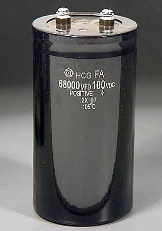
I will be getting 2 - 68000 uF, 100V caps from Apex Jr.
This should be good to start with?
As for the final power output, I say 1k as a ballpark figure. I know it will be less with the supply voltage I have, but that's fine.
There were several different ways to go about achieving the same end. The most sensible would have been to build a bridged design, using lower rail voltages. I chose the "brutal attack" as opposed to an elegant solution.
Each driver in the sub is 8 ohms, so the load (for now) is 4 ohms
Hi wg-ski,
My original plan was to use a single board for the whole amp. I then though about P2P when I laid out the MJL's on the heatsink. With my decision to have the heatsinks at rail voltage, the deal was done.
The plan from the beginning was for this amp (like it's predecessor) to be in a case, not in the sub itself. A little careful design with the case and some cooling fans and the heatsinks will be out of reach.
I did a sketch of the devices on the heatsink (now two) and it looks good.
AndrewT said:Hi,
What is the advantage of running Q5 & Q18 at under 3mA?
I would lower R4 & R45 to less than 100r maybe even 30r.
Smoothing @ +-20mF to +-40mF would be OK for 8ohm to 4ohm loading. If you envisage 2ohm loading then consider +-80mF to +-100mF, but you'll also need to reduce C6 to 150uF.
Using +-80mF you'll need about +-73Vdc to get your 1kW target. But reducing it to +-20mF needs the supply to be upped to about +-81Vdc when using a 4% regulation transformer of about 1.5kVA.
Alternatively,
build two amps each of around 500W into 4r0 (not 1000W into 2r0) and drive each speaker individually. You still get your 500W total into the box.
Hi Andrew,
Welcome aboard! Of course, as usual you are right about the drivers. Your observations are always valuable, as I'd never have seen that. I have reduced the resistors to 33 ohms.
I will be getting 2 - 68000 uF, 100V caps from Apex Jr.
This should be good to start with?
As for the final power output, I say 1k as a ballpark figure. I know it will be less with the supply voltage I have, but that's fine.
There were several different ways to go about achieving the same end. The most sensible would have been to build a bridged design, using lower rail voltages. I chose the "brutal attack" as opposed to an elegant solution.
Each driver in the sub is 8 ohms, so the load (for now) is 4 ohms
wg_ski said:
Unfortunately, that's one good way to get broken leads. Works ok with TO-3, but not the MJLs. Think about a motherboard/daughterboard arrangement. The followers, Vbe stack, and emitter/base resistors aren't likely to change as the design evolves. The front end might.
New amp of mine in progress does just that. Heatsinks will be at rail voltage (and those will be switched class H). Eliminates the themal pads, which add a lot to the overall thermal resistance - and it's not necessarily very consistent. The quicker you get the heat out to the thick part of the heatsink, the better the pulsed SOA you will actually have in practice.
Hi wg-ski,
My original plan was to use a single board for the whole amp. I then though about P2P when I laid out the MJL's on the heatsink. With my decision to have the heatsinks at rail voltage, the deal was done.
The plan from the beginning was for this amp (like it's predecessor) to be in a case, not in the sub itself. A little careful design with the case and some cooling fans and the heatsinks will be out of reach.
I did a sketch of the devices on the heatsink (now two) and it looks good.
Attachments
MJL21193 said:I'm scrapping the diodes in favour of a Vbe multiplier - more room for adjustment. Less hassle mounting a TO-220 to the heatsink than three diodes.
The .1 ohm emitter resistors is leftover from when this amp design was class B, I just didn't think to change these.
Fact is I don't have enough 5 watt emitter resistors of any value on hand to complete this, so I'll be picking up some more. Could go .33 ohm, like is in my P68.
I think that a Vbe multiplier is definately the better way to go. I don't like the idea of using a TO-220 device though (too much thermal mass). A BD139 would work much better.
I would still go higher than 0.33 ohms for the emitter resistors though and aim for a lower bias current (~30mA per device).
85mA per device with your rail voltages will dissipate about 100W of heat with the amp just idling.
And definately mount the Vbe mult trannie on top of one of the MJL's, not the heatsink.
Cheers,
Glen
I worked on a supposedly 2000W car sub amp in between my sick last two weeks... no way it could reach 2000W on 4 3055 and complimentary pairs... But it also used those metal bars for the high current paths
Hi,
now that you have two sinks, mount them fin to fin to create a tunnel and blow them. The gap between the transistor pins will be similar to the flat version you posted so the wire link to the PCB can be kept short if the PCB is aligned with the edge of the nearest fins.
_
[] = PCB alongside the fins with sinks facing fin to fin.
G.Kleinschmidt said:
I think that a Vbe multiplier is definately the better way to go. I don't like the idea of using a TO-220 device though (too much thermal mass). A BD139 would work much better.
I would still go higher than 0.33 ohms for the emitter resistors though and aim for a lower bias current (~30mA per device).
Hi Glen,
I was under the (false?) impression that the Vbe transistor should have a Vce greater than the +/-rail voltage. If this is not the case, I have a BD139 for the purpose.
As for the emitter resistors, I have the same advice for another member to increase these. I have some 0.82 ohm/5 watt on order for this.
The voices in my head says: "Johnny use the .33's you have - money doesn't grow on trees!! And look at the voltage you're dropping with those big resistors! Don't you know that somewhere in the world a poor amp is starving for voltage and here you are throwing it away!"
🙂
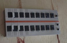
I put the heatsink back together last night. I glued a thick piece of plastic in between as an insulator.
See in the photo I'm recycling the devices from my original amp (the ones with the short leads). That means no sub till this is done!
The hardship I endure to save $50.00 worth of transistors.
Attachments
Nordic said:I worked on a supposedly 2000W car sub amp in between my sick last two weeks... no way it could reach 2000W on 4 3055 and complimentary pairs... But it also used those metal bars for the high current paths
Hi Nordic,
The wonderful world of car audio! It belittles our efforts here to build real amps with real power when some kid (could be a 40 year old kid 😉 ) says: " only 150 watts? I've got 45,000 watts out there in my Honda, and that's just the rear speakers!"

Using the heatsinks as rail conductors enables enough current carrying ability and I'll use solid #12 copper wire for the output lead.
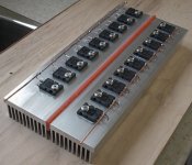
I have mounted the outputs on the heatsink(s). I made some aluminum dust and mixed it with the thermal grease and "lapped" each transistor in place. There is good conduction, both thermal and electrical between the case and the heatsink. I tested the electrical connection with a 60 watt light bulb and my 35 VDC bench supply.
The last 2 that are part of the CFP (Q6, Q28) are mounted with mica washers and thermal grease.
I made "bus bars" from 12 gauge and 18 gauge copper wire to supply the base of each output from the collectors of Q6 and Q28. There will be another one right down the middle for the output, after I get the right ballast resistors. These resistors will fit between each output transistor, under the bus bars.
Neat and tidy. Looks cool too. 🙂
Attachments
MJL21193 said:
Hi Glen,
I was under the (false?) impression that the Vbe transistor should have a Vce greater than the +/-rail voltage. If this is not the case, I have a BD139 for the purpose.
Hi
The Vbe multiblier transistor only has the biasing voltage for the output stage across it (about 2.4V), so you definately don't have to worry about its voltage rating here.
Cheers,
Glen
Thanks Glen. I've amended the schematic.
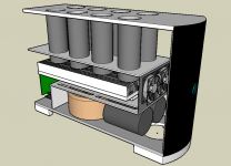
While I wait for parts, I thought I'd do some playing around with Sketchup to put some of my ideas on "paper". Having 140 VDC running through the heatsinks means they have to be out of reach. I could do as the tube dudes do, and cage it. That look is not appealing to me though.
I always planned a case for this amp, but having the heat source deep inside creates a problem. How to efficiently remove the heat?
I wanted to avoid fans, as they are noisy and for this much potential heat they might not be wholly effective. I've read about "chimneys" for heatsinks and that got me thinking. If I use temperate controlled fans with a chimney arrangement, this might be the way to go.
Looking at the attached picture, you'll see the 8 chimneys that start just above the heatsink and exit the top of the case. The case itself is a computer tower style about 12" high, 6" wide and 16" deep. 2 temperature controlled fans are at the front of the heatsink and a third fan, which will aways be running, is at the back on the bottom. The two front fans will be mounted on a rubber sheet (inner tube) to damp mechanical vibration.
On the bottom, there is the toroid and the big smoothing caps. An aluminum sheet separates this from the amp section. Also on the bottom is another 2 vent holes - one in plain sight and the other directly under the toroid. At the end of the heatsink is the circuit board for the amps front end (also a Linkwitz transform on the same board).
Yeah, it's complicated. It big, it's manly with exhaust pipes that resemble headers on V8 engine (in this case a 426 Hemi, ready for a '71 Cuda 🙂 ))))O>. It's a challenge though and worth the effort for bragging rights alone.😀:
The weekend is here - I can start building some of this.
Attachments
Keeping the fans at the end will create an uneven temp at the extreme ends of the heat sink.
You can even this out considerably buy blowing the air down at the center so it exits equally out the ends.
Look forward to your end results as I need a new amp for the same reason
Regards
David
You can even this out considerably buy blowing the air down at the center so it exits equally out the ends.
Look forward to your end results as I need a new amp for the same reason
Regards
David
- Status
- Not open for further replies.
- Home
- Amplifiers
- Solid State
- 1000 Watt Sub Amp: Design / Build