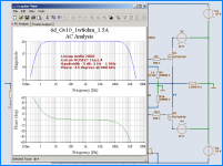
The AC analysis is great, too.
A good match for the very low distortion 😎
Bandwidth, -3 dB.....: 0.5 to 1,000,000 Hertz
- 45 degrees: 800 kHz
The idle current is set to 1.5 Ampere at +-18 Volt DC.
Gives a consumtion of 54 Watt.
And max output Class A is 3 Ampere ( 2 x 1.5 )
A good match for the very low distortion 😎
Bandwidth, -3 dB.....: 0.5 to 1,000,000 Hertz
- 45 degrees: 800 kHz
The idle current is set to 1.5 Ampere at +-18 Volt DC.
Gives a consumtion of 54 Watt.
And max output Class A is 3 Ampere ( 2 x 1.5 )
Attachments
Yeah, dear little Wavebourn
 True, in your ears those bad mosfets sound good
But not in my ears, no!!!
Lateral MOSFET especially made for Audio applications
have got that smooth nice sound of precision 😉
by the way, Wavebourn
I met 3 guys from Ukraine down at my gas station.
They are in sweden this summer to pick blueberry in our swedish forrests.
Then they sell these berries to swedish berry, jam factory
and get money and go back to ukraine.
Only the young one, 22, could speak with me in english.
His older comrades, like 45 years old, understood nothing
I helped them show way our best local electonics dealer.
Where is sold TV-sets, which they wanted to buy.
Probably to take with them home to ukraine.
Lineup - Audio Regards!
--------------------------------
My first day in Ukraine
( by an american from Chicago, I think )
True, in your ears those bad mosfets sound good But not in my ears, no!!!
Lateral MOSFET especially made for Audio applications
have got that smooth nice sound of precision 😉
by the way, Wavebourn
I met 3 guys from Ukraine down at my gas station.
They are in sweden this summer to pick blueberry in our swedish forrests.
Then they sell these berries to swedish berry, jam factory
and get money and go back to ukraine.
Only the young one, 22, could speak with me in english.
His older comrades, like 45 years old, understood nothing
I helped them show way our best local electonics dealer.
Where is sold TV-sets, which they wanted to buy.
Probably to take with them home to ukraine.
Lineup - Audio Regards!
--------------------------------
My first day in Ukraine
( by an american from Chicago, I think )
I like this amplifier very much. Hardly can be any simpler. It reminds of SE tube amplifiers. Probably doesn't measure very good since there is no feedback, but probably sounds very good 🙂 Does anyone know which JFET can be used for lower gain?
lineup said:Yeah, dear little Wavebourn
But not in my ears, no!!!
Lateral MOSFET especially made for Audio applications
have got that smooth nice sound of precision 😉
Yes, but in order to get all they are made for you have to use cryogenetically threated cables! 😱
Rookie said:I like this amplifier very much. Hardly can be any simpler. It reminds of SE tube amplifiers. Probably doesn't measure very good since there is no feedback, but probably sounds very good 🙂 Does anyone know which JFET can be used for lower gain?
which amp?where is the schematic?
umut1001 said:
which amp?where is the schematic?
On the first page, in the first post 🙂
did lineup made symmetrical supply..because an amp with output capacitor is not very good thing..not really hi-end concept..
yes it is.i made plh amp that has output capacitors.and ras10 single ended class a amp which has symmetrical pow sup..i can say that there is big difference.capacitorless single ended class a amps sounds clearer..
come on to technology baby rrsrsrsrs
come on to technology baby rrsrsrsrs
Hi,
I would use that series pass element as voltage regulator for the input and implement a high impedance current source for BC639.(BC550 and a base resistor is even better).
I would use that series pass element as voltage regulator for the input and implement a high impedance current source for BC639.(BC550 and a base resistor is even better).
this is TERRIBLE ...
last hour was 90 views in this topic (1 view each 40 seconds)
what have you done, umut1001 😀
by the way, i did some changes to my forums & blogs
http://lineupaudio.freehostia.com/forum
hope you like it, umut
and much thank you for reporting about your problems
this way i can improve to be a good audio forum
for all people in the world
... we will grow ... but never be same size as www.diyaudio.com
... because this is truly mission impossible 😉
Lateral MOSFET is what many diy builders use
especially of course the popular & easy to find good transistors
2SK1058, 2SJ162
Lineup 😎 regards to turkey
Twice The Power, Using 250 Watt EXICON
.
will take this circuit one step further
I used ECF10N20 + ECF10P20 for my Class A testings.
They are 'only' 125 Watt Lateral MOSFET.
Tjc = 1.0 C/W
Will try the more powerful pair:
ECF20N20 + ECF20P20
Max 250 Watt.
Tjc is as low as: 0.5 C/W !!!!!
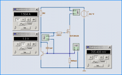
Here is spcie model I will use
My SPICE test Circuit for NMOS devices. To get: Vgs vs. Current
ECF20N20 shows Vgs = 1.30 Volt at 1.50 A and 20 Volt Drain-Source.
.
will take this circuit one step further
I used ECF10N20 + ECF10P20 for my Class A testings.
They are 'only' 125 Watt Lateral MOSFET.
Tjc = 1.0 C/W
Will try the more powerful pair:
ECF20N20 + ECF20P20
Max 250 Watt.
Tjc is as low as: 0.5 C/W !!!!!
Here is spcie model I will use
.SUBCKT ECF20N20 1 2 3
* ECF20N20
* EXICON 250 WATT NMOS LATERAL
* Tjc = 0.5 C/W
*
M1 9 7 8 8 MM L=1 W=1
.MODEL MM NMOS LEVEL=1 IS=1e-32
+VTO=0.362 LAMBDA=0.06 KP=3.097
RS 8 3 0.178
D1 8 9 MD
.MODEL MD D IS=1.0e-32 N=50 BV=250
+CJO=1.77e-9 VJ=0.1 M=0.28
RDS 8 9 1e+06
RD 9 1 0.265
RG 2 7 42
CAP1 7 8 900e-12
CAP 7 4 18.7e-12
D2 4 9 MDD
.MODEL MDD D IS=1e-32 N=50
+CJO=75e-12 VJ=0.1 M=0.768
.ENDS ECF20N20
My SPICE test Circuit for NMOS devices. To get: Vgs vs. Current
ECF20N20 shows Vgs = 1.30 Volt at 1.50 A and 20 Volt Drain-Source.
Attachments
Re: Twice The Power, Using 250 Watt EXICON
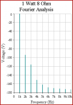
This is first result.
Idle power 100 Watt (2 x 20 Volt 2.5 Ampere Class A)
2SK389 JFET input
N-Channel Class A Push-Pull .. a la Quasi
using Exicon ECF20N20 250 Watt lateral MOSFET devices
Gain x14.6 (+23 dB)
Bandwidth, -3dB: 700 kHz
Attachment shows first version 1a from today
FFT Fourier at 1 Watt 8 Ohm output.
lineup said:
Will try the more powerful pair:
ECF20N20 + ECF20P20
Max 250 Watt.
Tjc is as low as: 0.5 C/W !!!!!
This is first result.
Idle power 100 Watt (2 x 20 Volt 2.5 Ampere Class A)
2SK389 JFET input
N-Channel Class A Push-Pull .. a la Quasi
using Exicon ECF20N20 250 Watt lateral MOSFET devices
Gain x14.6 (+23 dB)
Bandwidth, -3dB: 700 kHz
Attachment shows first version 1a from today
FFT Fourier at 1 Watt 8 Ohm output.
Attachments

- Status
- Not open for further replies.
- Home
- Amplifiers
- Solid State
- 10 Watt Single End, JFET input - Lateral N-MOSFET output