
I love your project and aesthetic. I have the same horn and to be honest it is not that attractive. I was thinking of carefully spray painting mine a lighter color to hopefully make it less obtrusive.
+1. Love the colours and the stands too!I love your project and aesthetic.
I admire your precise planning and execution of woodwork, simulation and measurements.
Don´t cry for a couple of [Hz], you won´t hear them anyway;-)
Guess a 10" in a closed cabinet makes for some nice bass in a home setting especially with such a quality driver.
Finding the final EQ filter can be much easier than looking at a graph. When you start from a reasonable filter function documented within REW, listen to your music and considering whether i.e. the midrange should be slightly boosted, the presence diminished or the brilliance again lifted: this can be done from within your digital playback device with a 15 band equalizer and later be translated into the DSP. In my experience, we build for an idealized function, which is barely an idea, and have to find out how this translates into our rooms. Pushing the EQ of the playback device will give you experience what is to be considered.
Good looking speakers! Still wonder why the horn is showing the dip-peak pattern at the lower frequencies, but you have had diffraction ruled out already before.
Good looking speakers! Still wonder why the horn is showing the dip-peak pattern at the lower frequencies, but you have had diffraction ruled out already before.
Thanks for the feedback everyone! The colour is Montana Gold Reef. As you can see it is a little more vivid in real life vs the swatch:

This type of paint has great coverage and sticks very well but it goes everywhere. I was as careful as I could have been but it is on literally everything in the workshop now!
This type of paint has great coverage and sticks very well but it goes everywhere. I was as careful as I could have been but it is on literally everything in the workshop now!
Here we have crossover mkiii (mkii was 24db at 1k) which is a 36db LR at 1khz.
What is both interesting and annoying is that dip at 2k from the previous 1.3k crossover has not gone away. Both the woofer and the tweeter both narrow around this area so, I think no matter where I plonk the crossover I will get a dip at or around 2k. The question is if it is better than mkii (https://www.diyaudio.com/community/threads/10-cd-horn-2-way.375829/post-6935423)? Probably not much in it between the two.


Distortion at 86db:


Distortion at an neighbour-rousing 95db:
Clearly the system is being pushed here but what I thought was interesting was the ramp and peak of the tweeter at/around 1000-2000hz. Clearly if this driver was to be pushed it needs a higher crossover.


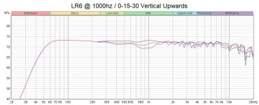
I tried to do some vertical polars but they became unreliable outside of 30 degrees. 1/6th smoothing but we get the idea. Luckily the listening position is only around a +/- 5 degree window from on vertical axis. However my knees get a very poor show.


Unwindowed step response:

Of course, I would love some critique 🙂
What is both interesting and annoying is that dip at 2k from the previous 1.3k crossover has not gone away. Both the woofer and the tweeter both narrow around this area so, I think no matter where I plonk the crossover I will get a dip at or around 2k. The question is if it is better than mkii (https://www.diyaudio.com/community/threads/10-cd-horn-2-way.375829/post-6935423)? Probably not much in it between the two.
Distortion at 86db:
Distortion at an neighbour-rousing 95db:
Clearly the system is being pushed here but what I thought was interesting was the ramp and peak of the tweeter at/around 1000-2000hz. Clearly if this driver was to be pushed it needs a higher crossover.
I tried to do some vertical polars but they became unreliable outside of 30 degrees. 1/6th smoothing but we get the idea. Luckily the listening position is only around a +/- 5 degree window from on vertical axis. However my knees get a very poor show.
Unwindowed step response:
Of course, I would love some critique 🙂
Attachments
What I am finding particularly interestnig to think about at the moment is trade-offs. Most specifically what tmuikku has talked about in avoiding the limitations. The old cliche we read here a lot about iron-laws and every speaker being a compromise rings true. Defiantly trying to make the perfect speaker out of a two way is tough unless you have a stockpile of beryllium.
To avoid the poor downwardly vertical polars I would need to add a mid.
To avoid poor directivity matching I would need to add a mid.
To avoid floor bounce I would need to lower the woofer and add a mid (or have the speakers on the floor)
To avoid distortion in the tweeter I would need to add a mid.
OR
Is it co-ax time?
BUT, these issues are kinda moot as I don't play material very loud at all (distortion dealt with), I have limited vertical movement in listening position (vertical polar dealt with), I can begrudgingly live with floor bounce and I could change horns to get the directivity matched (maybe)
So far these speakers sound amazing and the combo is by far the best I have made/heard in my house. But I will keep going til it's better.
I would not think about the next better speaker before you gathered experience why this speaker does sound its way and if you like it in comparison with other topologies. This takes time. I started to think a lot about pattern width (would love to have a constant directivity device >=100 degree).
I am not yet convinced that what you call a crossover dip is actually caused by the radiation pattern and dividing filters. My prototypes with 12-inch drivers didn’t show this problem with in-room measurements (MMT), where it should become apparent if energy is lacking: https://www.audiosciencereview.com/...n-room-measurements.13540/page-21#post-831911
And the woofers in my case would even beam earlier than your 10-inch drivers, while my Celestion-JBL combo is certainly less advanced than the Faitals you opted for.
Did you measure the in-room response away from the walls? Can we be sure this is not SBIR? Or maybe something else?
Work on dialing in EQ. What you cannot change is pattern, for now, but you can do everything to control linear distortion until the spectrum is just right. For example the sound of my speakers benefited from boosting the mids and lower mids, as well as brilliance, but with presence a bit removed. In my room, this made a big difference. If your horn is a CD waveguide, it might have to much presence energy. SBIR causes havoc to lower mids.
While you are still on it try some shallower slopes for xo, check out if you can hear a difference. I've found some configurations sound more exciting than others for lack of better words despite very similar frequency response.Of course, I would love some critique
While my DSP settings might have an error contributing to the difference also in the simulation program there is many ways to make very nice frequency response while the timedomain is different, namely the step response and group delay. I can' say what is it, I just encourage to experiment.
ps. your feet don't mind the sound too much 😀 You could measure the vertical response laying the speaker on its side, rotating it horizontally. Feed the data into VituixCAD and see the DI and power graphs as well as how the polar response looks like, early reflections and their DI is also available.
Horizontal polars are pretty good I suspect but the vertical might contribute to the sound depending your listening distance, speaker and room height for example, and the xo, c-c. First reflection (or perhaps few first order vertical reflections) come quite early and sum with the direct sound coloring it some. I can't say of this is too audible, but it still is something you could experimeny on at some point if you are interested, perhaps with the next project if not this one as it looks finished already. If you like the sound now, enjoy it! 🙂
Last edited:
I'd think you could run that 10" woofer crossover up to 1.6k and achieve 90 degree horizontal directivity right there.
To avoid the poor downwardly vertical polars I would need to add a mid.
To avoid poor directivity matching I would need to add a mid.
To avoid floor bounce I would need to lower the woofer and add a mid (or have the speakers on the floor)
To avoid distortion in the tweeter I would need to add a mid.
OR
Is it co-ax time?
You could measure the vertical response laying the speaker on its side, rotating it horizontally. Feed the data into VituixCAD and see the DI and power graphs as well as how the polar response looks like, early reflections and their DI is also available.
Horizontal polars are pretty good I suspect but the vertical might contribute to the sound depending your listening distance, speaker and room height for example, and the xo, c-c.
There's Kimmo's rule of thumb for optimizing power response with vertical c-c of 1-1.2x wavelength at xo frequency, or vice-versa. As I understand right now this is for LR4 and time aligned sources with wide radiation at xo frequency.
https://www.audiosciencereview.com/...-on-the-vertical-radiation.23239/#post-775837http://www.htguide.com/forum/showthread.php?44128-VituixCAD-v2&p=639178&viewfull=1#post639178
Based on this, you'd time align the drivers and go with a LR4 xo frequency that has 1-1.2x wavelength of the c-c of cone and horn. I guess this would be around 1kHz. The horn wil be wide there which as I understand aligns with the rules. But I'm trying to catch up on this myself, can't say I have firm grasp. Wide sources can be simmed easily in VituixCAD with the default drivers.
Yeah, basically there is no way to make the vertical polars perfect with so short wavelengths and non coincident drivers. Above some hundred hertz, solely due to driver frames, SPL requirements and other stuff. MEH would allow close enough spacing for point source summation, coaxial, woofer with fullrange system. Two way with waveguide tweeter won't ever get into 1/4wl c-c so the next question is what the c-c should be then. Basically there is possibility to point the lobes somewhere playing with the c-c and while there is not too much data on this I believe, blind listening tests, I'd speculate similar sound of the first reflections to direct sound would help them integrate better with the direct sound in the hearing system. But this is just speculation since I do not have sufficient background on hearing systems, or not too much experience on loudspeakers for that matter 😀 Anyway, a possibility to tune the system and affect its sound, tool in the tool box.
Cheers guys.
Yes, on all points, really! I need to get to grips with VituixCAD for the polar simulations. I am not quite sure how I would work out driver z-offset moving over to Vituix.
It has been a while since I routinely went through multiple instances of multi-way crossover design. At the moment I capture all data in REW, use the VituixCAD baffle sim to mould my nearfield measurements and then merge with far-field data and the XSim 3D for filter design. It would be nice to consolidate that a bit.
One thing I can't remember is whether or not to time align all measurements in REW before I make the drive z-offset? Or whether to set minimum phase before I set driver z-offset. It's been driving me nuts and making my sims not match the real world and they need time adjustments after the fact.
Anyway, I will continue to experiment with slopes and crossover points, I am sure there is a sweet spot in there somewhere. I may re-measure them once I remember the above niggle and plan out a few different networks to test and measure in one go. I have a Victorian terraced house in greater London and the walls aren't thick so I need t give my neighbours a break from what must sound like tropical bird torture.
As I say, vertical polars aren't really an issue as our listening window is pretty narrow in that respect but you know, it's something to be fiddled with. I would lay is sideways to do proper measurements but because the horn free-stands on top it is a hassle so I can't be bothered. I'd have to strap it or something. This is the draw back or making the system modular but also means I can try different horns, adding a mid, or whatever I fancy to it. I wanted to futureproof my experimentation possibilities.
An MEH is certainly something I want to try at some point but I want to get a decent mitre saw beforehand.
I'll keep you all appraised of the progress 🙂
Checkout the measurement documents, links are top of the page here https://kimmosaunisto.net/, there is one for REW.
This feels quite hard at first to get the head around how it all works out, hopefully this helps 😀
Basically, one would use two channel measurement setup, the other channel ensures reference for timing. Then, all you do is make sure you keep the distance from mic to your rotation axis constant and convert the measured impulse responses to frequency responses keeping same windowing across all the measurements. Usually rotation axis is chosen middle line through centers of the drivers along your baffle plane, around which you would rotate the DUT while taking off-axis measurements.
Each transducer is measured separately and you move either the DUT or mic so that mic is center axis of the transducer, remember to keep the distance the same. Now, after done with the measurements the relative distance to the sound source is in the measured impulse responses as long as you kept the same rotation axis / reference plane on all the driver measurements (and used the two channel measurement method, to have accurate timing preference). All you have to do now is to convert the IR to FR using exactly same windowing settings so that the timing is preserved (at least for ARTA, not sure how the REW measurement procedure goes). This all is in the measurement manual.
Done like this you don't have to worry about the Z offset anymore since it is baked in to the measurements and as accurate as you kept your measurement setup. All you have to do is vertically (and perhaps horizontally) move the measurements of each drivers within the crossover simulator to match the real unit you measured. Because, we measured each driver on axis, the driver (the measurement data) loaded in VCAD needs to be moved to reflect your construct. If you did full 360 horizontal and vertical measurements you could visualize this a balloon per driver. Basically you just select a reference axis/point you want to design against. Usually this is the listening axis while you are seated. If your speakers are made so that the tweeter height is the listening height you leave the tweeter Y and X coordinates to zero and then put negative Y for your woofer, for example -25cm or so in your case, what ever is the actual distance of woofer center to the design axis, the listening height.
Once more, each driver in VCAD simulator main window represents a set of measurements (of that particular driver) and the driver coordinates just move the set of measurements around. You can exploit this as you like, very flexible system, but sticking to the measurement manual is the right way to get started. The VCAD main program does not model your speaker, doesn't create local interaction with the physical speaker construct. The construct is already in the measurement data you use and the graphs show how it all combines at the "listening position". Listening position in the simulator, which all the graphs reflect, is made up of your design axis (0,0,0 coordinates on the drivers), listening distance (Options), toe-in (Ref-angle, top of the main window). If you want to see what the response is for example standing up, just move the Y coordinates of the drivers to reflect the situation. If your sitting height was 90cm and you are 180cm tall this would mean Y coordinate of -90cm for tweeter, -115cm for woofer.
If you follow the manual accurately (enough) then you can be confident all the data is good and can rely on the simulation. You can then inspect the acoustic radiation of your speaker to any direction and inspect the useful totals like sound power and early reflections, polar graphs, phase info and what not. Though, there is some error as you inspect radiation outside the coordinates you have actual measurement data for. The measurement procedure and how the simulator uses the measurement data enables you to have more accurate data where you need it the most. This might come handy at some point but most of the time you would be golden with the procedure in the measurement document.
What you can do with reasonable accuracy is play with the c-c distance and tilt of the ways etc. Very powerful.
Last edited:
What you can do with reasonable accuracy is play with the c-c distance and tilt of the ways etc. Very powerful. All that is required from the designer are accurate measurements, or knowledge what is accurate and what is not, then some imagination to put it all together and fiddle around, visualize the system 😀 greatest problem with audio is that you cant see it, otherwise it is not too complicated, just varying sized waves interacting with varying sized objects 😀
I just had a refresher on the VituixCAD manuals and it comes flodding back to me. I have aUMIK-1 and USB mics have the latency issue that needs manual Z finding which isn't an issue really but whether or not to use the auto alignment in REW is my boggle.
I think I may have settled on a filter set up with an LR2 @ 1300hz. It doesn't look as pretty as the previous but it does control the distortion peak from the HF10AK just below 2k a bit better. At 86db is is safely under -50db THD until a suspicous looking spike at 290hz.
There doesn't seem to be any compromise that fills in the off peak dip around 2k but I will have to live with this. Both the woofer and the horn seem to naturally recess here so whichever way you have it (higher or lower crossover) there will be a trough.
The step response isn't what I expected. I have a 0.14 millisecond delay on the woofer to get the null to deepen to the max. I guess the drivers aren't time aligned but are in phase at crossover. Looks more like an LR4 step response.
Speech does come through cleaner, I feel, which is important as these are for everything from watching the news to bangboomcrash movies to late night quiet music sessions.
Last edited:
14 ms feels like a crazy value - that is something like 4.8 meters difference
Corrected
 0.14
0.14I do not understand why your step response has this wiggles where the signal starts. Is the woofer interfering with the compression driver/playing to early?
Apart from that I predict with this tuning you will find yourself bringing down the treble after a while. The off axis shows quite a bit of lost energy around 2k, the problem with small waveguides. The presence band could be standing out just a bit too much.
If the problem cannot be solved both on-axis and off-axis, due to the smallish waveguide, you might find yourself choosing between applying EQ to control treble or trading some on-axis linearity at the first hand for a more balanced tuning. This of course is easier to visualize with a set of angled measurements both vertical and horizontal.
- Home
- Loudspeakers
- Multi-Way
- 10" + CD/Horn 2-Way