Hi,
I am a new DIYer and am trying to build Salas Ubib. I have done some soldering on practice PCB board and this my first real project. So far I have soldered the resistors (pics below). My question is how do I verify before turning on the power that the solder joints are good? The resistors are firmly in place. When i put a multi-meter on the solid solder on the PCB i'm getting the correct resistance. I have also checked there is no shorting, with continuity test. Are there other tests?


I am a new DIYer and am trying to build Salas Ubib. I have done some soldering on practice PCB board and this my first real project. So far I have soldered the resistors (pics below). My question is how do I verify before turning on the power that the solder joints are good? The resistors are firmly in place. When i put a multi-meter on the solid solder on the PCB i'm getting the correct resistance. I have also checked there is no shorting, with continuity test. Are there other tests?
Looks good so far. You might try a little longer dwell time so the solder can flow through to the top side.
Also when done its best to clean off the flux with some iso alcohol.
This makes it easier for a good visual inspection.
I have learned the hard way that even a hairline solder bridge can cause trouble.
The testing you're doing is great and certainly helps to minimize errors.
Slow and steady with lots of checking is the way I like to go.

Solder > check². It's a bit like measure twice, cut once.
Once a PCB is populated it's hard to get a true reading with a DMM so rely on visual inspection and experience as you do more soldering. Usually with builds there are test points and instructions to follow before and after power is applied.
Once a PCB is populated it's hard to get a true reading with a DMM so rely on visual inspection and experience as you do more soldering. Usually with builds there are test points and instructions to follow before and after power is applied.
This. ☝️Looks good so far. You might try a little longer dwell time so the solder can flow through to the top side.
...
Slow and steady with lots of checking is the way I like to go.
Try the following:
(Suggest you practice with a resistor).
Wipe your soldering iron tip on your damp (not soaked) sponge.
Apply a tiny blob of solder to your soldering iron tip. Just enough to make a small puddle. (This is called whetting; the solder on the tip's surface will promote heat transfer).
Place the tip against both the component lead and PCB pad. Hold for around 3 seconds.
Now apply solder slowly. A tiny bit at a time. The flux from the solder will clean off surface oxides and the solder should flow freely over the heated metal parts.
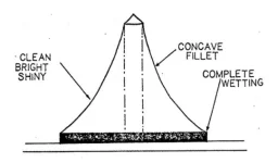
The finished solder joint should have a concave meniscus. Think Mt Fuji.
If you end up with a bit too much solder (as in your pics), re-applying heat should enable the extra solder to flow through the plated through-hole to the other side.
For a beginner I highly recommend using Cardas Quad Eutectic Solder. It does a lot to uncomplicate the process because it has excellent whetting and flow characteristics.
If all else fails, you can cheat by using a bit of flux. But be sure to clean it off thoroughly.
Agreed, a certainty even for professionals (which I'm not): I've used it for so many years and it really seems to be the best in every circumstance although of course the cost is adequate to its good fame, however its availability at least in my area seems to be currently not what it once was.For a beginner I highly recommend using Cardas Quad Eutectic Solder.
In my recent experience a good 60/40 alloy does seem to get a very similar good job at a (much) lower price.
In my opinion one of the strong points of Cardas is also its reliability over time.
Anyway it should be noted that lead in solder alloys is currently banned in several countries.
In my view, the welds look properly shiny, but you'll see that with practice they will get better and better.So far I have soldered the resistors
What is a good temperature for soldering good quality boards? I'm using 350 degrees celsius. But feel like its a bit too low?
Shiny depends on the type of solder. Use normal lead-free and it will look matte which is good.In my view, the welds look properly shiny, but you'll see that with practice they will get better and better.
My few cents:
- always keep the iron clean. A scourer is better than a sponge. It's good to have a rosin at hand. Put the iron into it, apply a bit of solder o it, then clean on the scourer. The tip should be shiny before soldering.
- preferably cut the leads before soldering. Use flat precision cutters.
- find the correct temperature for given solder, PCB and iron power combination. Indicator of the correct temperature is when the solder cover the pad rapidly and act as "liquid" that's wetting the PCB and the lead. With too high temperature the flux vaporise and you're making a dry joint.
- ideal shape of the joint is concave
- consider use of flat tip, like 1 - 2 mm width. It's fine for most hand work, better heat transfer, shorter soldering time possible.
- heat the pad and the lead simultaneously, they both need to be hot for the solder to catch. It all should go pretty quick, around 3 seconds should do
- from a practical point of view, visual inspection is all we diy mortals can do for QC
Attachments
Last edited:
What is a good temperature for soldering good quality boards? I'm using 350 degrees celsius. But feel like its a bit too low?
Most of my soldering life I have been using a Weller TCP "magnastat" type soldering iron with no.7 coded bit, which regulates to around 370°C.
Nowadays, my Magnum soldering iron has presets for 320°C and 380°C, plus a user-selectable temperature between 100°C and 450°C, which I keep at 210°C for plastics work. For soldering, I use the 380°C preset.
The size of the bit is as important as working temperature. It should have sufficient thermal mass to maintain heat during soldering*. For this reason, I have an assortment of bits**.
*More modern soldering irons like the venerable TS100 and the like seem to suffer less from this effect, having apparently quicker regulation times.
**Size and shape of the bit should also match the size of the work (e.g., terminals vs SMD).
Thanks everyone for the feedback. I have used many of the them in the followup soldering of the components. Its not perfect but seems better than the first pics i uploaded before.
Here are the main changes I have done
1. Increased the temperature from 350 degrees to 380 degrees celsius.
2. Changed from really pointy tip to tip with more surface area.
3. Used the reflowing strategy mentioned above to reflow where the solder was more.
4. Used a thinner 0.8mm solder wire instead of the thicker solder wire i used before.
First, learn how to bend leads and put parts in holes properly. If you have components with lettering on them, bend the leads so that the part value is readable on top. When you turn the board over to solder you can bend the leads out a little to keep the component from falling back down out of the holes (otherwise you can tack in parts with solder from the top before soldering the bottom). I would suggest to use a chisel tip, maybe on its side to heat the lead wire and the solder pad at the same time (by contacting both at once). The faster you can get in and out with a good solder joint filet the better. Use enough heat so it goes pretty fast. You should be able to see solder flowing down into the PCB hole as you feed in solder. Three seconds is a long time for me. Maybe more like one second or a second and a half for common PCB joints. Choose a solder wire diameter that allows you to control how much solder you feed in for the type of joints you are doing. Figure out how much is the right amount of solder for a particular solder wire diameter and joint type. Once you get the right amount, try to use the same amount for each subsequent joint. For example, if you find that feeding in about 1" of solder wire makes a good joint with a properly shaped filet, the try to gauge feeding in that same amount for similar sized joints. The more methodical you can get with it the more uniform your solder joints will turn out. If you find you have to feed in 4" of solder maybe you are using too small of a diameter of solder. OTOH, if you have to feed in 3/8" maybe the solder wire is too thick to control uniformity well.
When you are done, clean off the flux with 99% isopropyl alcohol and a disposable acid/flux brush, or flux remover. Inspect the joints for quality. If too much solder, too little, burnt solder, etc., then clean it up and fix it. A good quality flux remover braid like Chem-wik can be very handy (in the right size, I use #2 for the smaller stuff, and #4 for most other).
When you are done, clean off the flux with 99% isopropyl alcohol and a disposable acid/flux brush, or flux remover. Inspect the joints for quality. If too much solder, too little, burnt solder, etc., then clean it up and fix it. A good quality flux remover braid like Chem-wik can be very handy (in the right size, I use #2 for the smaller stuff, and #4 for most other).
Last edited:
Forgot to mention, it can be helpful to use a little bit bigger tip than seems the perfect fit. Usually that works better than using a tip that is too small.
Also, it helps a lot to have something to hold the board very steady while its being soldered. A pair of Hakko soldering vises are great, but unfortunately not cheap.
Also, it helps a lot to have something to hold the board very steady while its being soldered. A pair of Hakko soldering vises are great, but unfortunately not cheap.
Last edited:
For stuff like that I'd use a 1.6-3.2 mm wide chisel tip. 380 ºC (~700 ºF). The board is gold plated so you should have no trouble getting the solder to flow and wet (or whet) correctly.
If I was to nitpick, I'd say that you use too much solder. You and I have that in common then... 😉
And +1 for bending the leads with needle nose pliers before inserting the components into the board.
Tom
If I was to nitpick, I'd say that you use too much solder. You and I have that in common then... 😉
And +1 for bending the leads with needle nose pliers before inserting the components into the board.
Tom
Oh... And I don't know if you're adding extra flux. If you do, stop it! There's already flux core in the solder.
Tom
Tom
Lead bending jigs, various kinds are available. You'll find them useful.
https://www.digikey.com/en/products/detail/sparkfun-electronics/TOL-13114/5623215
And throw away those long, thin pointy tips. They're awful.
https://www.digikey.com/en/products/detail/sparkfun-electronics/TOL-13114/5623215
And throw away those long, thin pointy tips. They're awful.
Getting both pieces of metal (leads & pad or terminals ) to the same temperature is essential to getting a good joint. This is learned by experience.
When both metals are at the same temp, the solder will flow perfectly and appear very shiny.
When both metals are at the same temp, the solder will flow perfectly and appear very shiny.
Something else occurred to me: Try to feed in the solder uniformly over the time you will be heating the joint. This keeps some fresh flux on surface the whole time. OTOH, if you push the solder in too fast before the joint is ready for it, then you may run out of flux before the joint can fully flow. Too slow and the solder already melted may run out of flux. Its a matter of timing and watching what's happening.
Last edited:
Yes, this is something i need to practice more.If I was to nitpick, I'd say that you use too much solder.
What helped me understanding soldering better is pretinning of several test pieces of wire. Clean tip, bit of solder on it. Apply some heat on the wire, then feed the solder. Besides this, I enjoy soldering in a way where I have a really solid connection (so no jiggly components when soldering) and visualise the solder as a 'sealant' of a mechanical proper connection.
Practice a lot, and be sure to not disturb the joint while it is still hot.
- Home
- Design & Build
- Construction Tips
- Question about soldering