It should! This uses a short cylindrical extension (from phase plug exit to the driver's exit), which does show a small resonance. Worst case that can be equalized, but based on the various measurements that you and others have done of extensions with similarly unruly impedances, I doubt it'll make for big issues.@Scgorg - will you manage to fit it into an existing throat of one of the BMS drivers?
- It's always possible to add an extension, but then the impedance mismatch can be a problem: http://www.at-horns.eu/ath300ex.html#CDW
(I have no feedback on that experiment, haven't tried myself.)
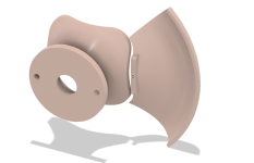
BTW, I've just finished assembling the flat-DI petals -


It went absolutely smoothly, easier than ever before. Seems like I've finally managed to learn how to make these kits.
All petals assembled at once, each joint has three short splines, very straightforward workflow, no jig required.
For me there's nothing to improve, I've published the model as A460D: https://cults3d.com/:2404194
I used a 1K PU glue this time (ICEMA R 145/12).
First measurements hopefully tomorrow.
Last edited:

Is there a feature that could be added to the back for an elastic band to go around and pull everything together?
@mabat what about flat-DI WG for the 1.4 inch drivers? (although I don't even know if I need more waveguides, lol)
And wouldn't it work with a 520 waveguide and appropriate extension? If I understand correctly, the diffraction at the throat of the waveguide sets the stage for a flat MDI? Or should it be the whole curve?
And wouldn't it work with a 520 waveguide and appropriate extension? If I understand correctly, the diffraction at the throat of the waveguide sets the stage for a flat MDI? Or should it be the whole curve?
This is the same waveguide, just for a 1.4" throat (without any further optimization):


The question is whether this is good enough.
There's no way how to widen further the directivity of the existing Gen2 horns just by a different adapter. Those were designed so that there's a smooth blend of the directivities you see in the above graphs at 800 Hz and at 15 kHz.
The question is whether this is good enough.
There's no way how to widen further the directivity of the existing Gen2 horns just by a different adapter. Those were designed so that there's a smooth blend of the directivities you see in the above graphs at 800 Hz and at 15 kHz.
When I looked into slicing a WG (taking the ST260 stp file) to make masters for casting, at one point I was thinking about a connection point on each petal/quadrant for some kind of jig with threaded rods that holds them in place for assembly. 😀Is there a feature that could be added to the back for an elastic band to go around and pull everything together?
By the way, as I recall the quoted price for these 2 parts SLA 3D printed was around $30 shipped from one of those PCB manufacturers in China. Then using mold making silicone to make 2 molds, 1kg silicone would be around 25 EUR or so. Then, I'd use Jesmonite AC100 or Acrystal, easy to handle stuff, to cast 2 bases and 8 quadrants, The cost of these is around 13-16 EUR per kg. The Acrystal user guide mentions that it can be cut by adding sand, and in general I'd think lot of possibilities for nice appearance and finish, which would be the main point of this, compared to work involved in finishing up 3D printed things.
Attachments
Thinking about it, it's probably good enough, as most 1.4" drivers collapse above ~12 kHz anyway.... The question is whether this is good enough.
First measurements hopefully tomorrow.
A460D + DFM-2535, roughly 0-10-20-30 deg:
Here we're back with the usual stuff...
There's simply a price to pay for a true constant directivity.
And now back to the BMS 🙂
Last edited:
I don't know what's the exact origin but the result is a simple resonance, it seems. This should not be difficult to get rid of on the signal level.
A460D + Lavoce DF10.171K:

A460D + Lavoce DF10.171K:
It is fairly wide, around 90°.
BTW, this mounting is just great, from what I can tell so far -


No short Allen keys needed.
BTW, this mounting is just great, from what I can tell so far -
No short Allen keys needed.
Last edited:
This is the predicted performance of the A460D in the good old Ath 2x2 format.
At least I hope this is the one that was finally made.

At least I hope this is the one that was finally made.
These are the wavefront areas, assuming they are all spherical, perpendicular to the walls.
For z > 0 that's the waveguide itself. For z < 0 it's either an adapter (Gen2) or an exit section of a driver.
A460G2 + BMS4554 adapter (S140):

A460D + DFM-2535 exit section:

All the midrange peaks and dips are probably the result of the pretty large mismatch in the second case, together with a lower throat impedance overall (?). For wide-radiating waveguides, it seems we really want drivers with the shortest exit paths as possible, as many have already advocated in the past, for this very reason. Of course this can be EQed, the more so today with a DSP it's very straightforward, but it's obviously an acoustical problem.
For z > 0 that's the waveguide itself. For z < 0 it's either an adapter (Gen2) or an exit section of a driver.
A460G2 + BMS4554 adapter (S140):
A460D + DFM-2535 exit section:
All the midrange peaks and dips are probably the result of the pretty large mismatch in the second case, together with a lower throat impedance overall (?). For wide-radiating waveguides, it seems we really want drivers with the shortest exit paths as possible, as many have already advocated in the past, for this very reason. Of course this can be EQed, the more so today with a DSP it's very straightforward, but it's obviously an acoustical problem.
Last edited:
That said, it doesn't mean that the long adapter above is "boring":

- This is the corresponding FR (BMS 4554, again):

Obviously there's a lot of degrees of freedom at the lower end. Only some of those are in our control though, the rest being in the driver.
- The above is of course limited by the existing Gen2 body, which is fixed. Releasing those constraints and making a new profile from scratch could lead to a smoother result (or not).
- This is the corresponding FR (BMS 4554, again):
Obviously there's a lot of degrees of freedom at the lower end. Only some of those are in our control though, the rest being in the driver.
- The above is of course limited by the existing Gen2 body, which is fixed. Releasing those constraints and making a new profile from scratch could lead to a smoother result (or not).
Last edited:
This is for A460G2 and the 36-STD-1 (1.4") adapter:

The different adapters simply connect whatever throat diameter&angle to the main body with a smooth expansion.
It's optimized completely differently, but the results are always like this (it's obviously tied to wall curvature).
The problem is that there's also an expansion in the phase plug and that's completely out of our control, typically not even known.
- Wondering what's the expansion in the BMS phase plugs. Does anyone know? I think it will be very small but I would need to destroy one to find out.
Last edited:
- Home
- Loudspeakers
- Multi-Way
- Acoustic Horn Design – The Easy Way (Ath4)