The base parts printed. I believe this is the best driver mounting method I have so far. The last piece can be used as an adapter for different throats / exit angles, etc. (already working on one for the BMS 4554)Finishing the flat-DI kit - "the classic".
And the petal assembly -
Last edited:
Would you mind sharing some details like the driver and woofer you used and crossover?It's still sunny in Warsaw, so I thought I'd share 🙂
I use what I had available, although I generally like all the components.Would you mind sharing some details like the driver and woofer you used and crossover?
RCF 940 drivers in ATH A520G2 (great waveguides by the way)), Faital pro 18fh500 in U-frame (40-500Hz), plus 2x10'' servo subs (~17-90Hz).
Hybrid crossover - combo of passive, active and total equalization. Passive crossover ~ 500 Hz, capacitor and l-pad on the driver, 2nd order on the woofer. I haven't fine-tuned it yet, it'll need some more tweaking but still sounds good. Subs and midbasses crossed by Lyngdorf 1120. And overall equalization also in the amp.
Unfortunately no crossover pictures at hand. Room behavior looks like this:
Thanks, seems to me like a very nice setup. The u frame is like an box with no back, right? Did you use any damping material like in an aperiodic enclosure? I hope I'm not getting too far off topic.
PMed you, let's not hijack the thread.I hope I'm not getting too far off topic.
FYI:
Lavoce
Same as before 8 BQ 800Hz
I was close to get the 5530ND but ended up with 18sound 1095... still curious I have to say and have som regret about it actually,,,
The rosso seems very promising however .... 🙂
//
The rosso seems very promising however .... 🙂
//
I spent some time working on freestanding waveguides for these small exit drivers, and I must say the results are really promising. It is possible to obtain a flat DI/power response all the way up to 20khz if one wants to, while barely sacrificing smoothness. This particular example has a total diameter of 340mm.

@Scgorg - will you manage to fit it into an existing throat of one of the BMS drivers?
- It's always possible to add an extension, but then the impedance mismatch can be a problem: http://www.at-horns.eu/ath300ex.html#CDW
(I have no feedback on that experiment, haven't tried myself.)
- It's always possible to add an extension, but then the impedance mismatch can be a problem: http://www.at-horns.eu/ath300ex.html#CDW
(I have no feedback on that experiment, haven't tried myself.)
Last edited:
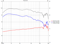
You are onto something with the BMS 4554 here! How did you manage to dampen/shift the 18kHz resonance of the membrane?I have also some very very quick measurements/comparison of ROSSO 65CDN-T and BMS 4554 with a basic adapter of 33.1 deg angle.
(I didn't have the right bolts so this was only put loosely on a stool.)
A520G2 waveguide, everything same for both.
BMS 4554 alone:
View attachment 1367490
Here you have a driver reaching 20 kHz with ease. Not so much at the lower end though.
View attachment 1367491
I'm using DE360 cause of the great behaviour up to 20kHz but having a driver with similar behaviour and can be used an octave lower ... that would be great!
I actually think I have a pair of 4554 in one of my PA speakers I did years ago ... as infills to my bigger ones with the Coax. Never needed and used them a lot.
I have no idea, I'm not aware of any resonance, nor I tried to damped it - If I did, it was utterly unintentional 🙂How did you manage to dampen/shift the 18kHz resonance of the membrane?
Simulated A460G2 with the default throat adapter T520-36-STD-1 and then printed and measured, driver is ND3T.
Both have rotation axis at the mouth, except my rig is bit flimsy and rotation axis about 2cm in front of the mouth plane. The flimsines is likely result why measured seems to have little bit wider coverage. Otherwise agreement between sim and measurement seems very good despite my poor gluing job 😀
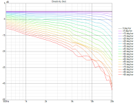
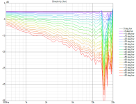
ps. the standard rotation axis of sims, at throat, gives much higher DI with deep devices. So if anyone is playing with simulations to find suitable device, make sure the rotation axis making the data is adjusted as necessary, or Z offset in VCAD of course, to match data of rest of the system.
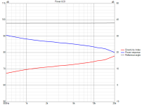
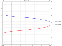
the ND3T has output well beyond 20kHz, here 0 and 15deg data on first image and 30deg on the second, not too bad. 30deg trace and beyond shows dip from ~13kHz up tho, likely not audible at all as it's quite narrow bandwidth.
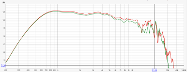
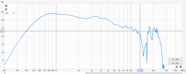
Both have rotation axis at the mouth, except my rig is bit flimsy and rotation axis about 2cm in front of the mouth plane. The flimsines is likely result why measured seems to have little bit wider coverage. Otherwise agreement between sim and measurement seems very good despite my poor gluing job 😀


ps. the standard rotation axis of sims, at throat, gives much higher DI with deep devices. So if anyone is playing with simulations to find suitable device, make sure the rotation axis making the data is adjusted as necessary, or Z offset in VCAD of course, to match data of rest of the system.


the ND3T has output well beyond 20kHz, here 0 and 15deg data on first image and 30deg on the second, not too bad. 30deg trace and beyond shows dip from ~13kHz up tho, likely not audible at all as it's quite narrow bandwidth.


Last edited:
Thanks. This is roughly what you can hope for with majority of the 1.4" drivers, when used that way.
- I think the sim will give you the acutal DI for the full-sphere data (as it should be done). The exact rotation origin matters to a degree, but a few cm don't really matter much, typically. If you have only data for 0-90, then it may be the bigger part of the difference.
- I think the sim will give you the acutal DI for the full-sphere data (as it should be done). The exact rotation origin matters to a degree, but a few cm don't really matter much, typically. If you have only data for 0-90, then it may be the bigger part of the difference.
Hi, yeah there is various ways to calculate it, VituixCAD options has also many settings that affects it. I got full 180deg data measured in 15steps so interpolation is another possible source for some error.
I think this rotation axis stuff is almost irrelevant when comparing results between each other, although the deeper the device the more there is difference where the rotation axis is. Why I'm posting about it is that problems arise if VituixCAD project has various drivers simulated / measured / handled differently, as I had 😀 I did simple sims of woofer box with diffraction tool, so rotation axis is at baffle, and simulated waveguides with ABEC so need to make sure the rotation axis is also at "baffle", or Z offset compensated, so that the whole system is "realistic". When full speaker is assembled and ready and one starts to measure it to confirm that complete speaker measures like simulated, then there is only one rotation axis, the baffle plane.
Here just in case difference of throat and mouth spin simulation zoomed in, all with 15deg steps.
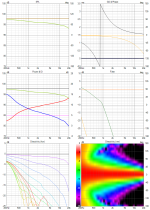
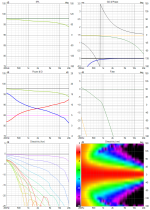
Here measured data, this is not normalized but the DI should be ok. All of these are "measurement data" and VituixCAD calculates DI with same settings for all these. My measurement windowing is likely also making issues here, seen on low end how the ~200Hz is louder from behind than from front, which is either problem of windowing or the device making sound to back more than to front 😀
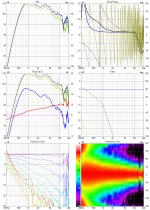
Age old "problem", getting good data is not exactly trivial, needs some work and concentration to get to know what the data represents and whether there is error and some estimate how big it is.
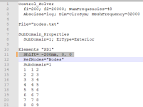
Btw. I made the mouth spin simulation by offsetting nodes directly in solving.txt, didn't remember how to do offset within ATH script. ABEC project was created with the ath script that came with purchase.
I think this rotation axis stuff is almost irrelevant when comparing results between each other, although the deeper the device the more there is difference where the rotation axis is. Why I'm posting about it is that problems arise if VituixCAD project has various drivers simulated / measured / handled differently, as I had 😀 I did simple sims of woofer box with diffraction tool, so rotation axis is at baffle, and simulated waveguides with ABEC so need to make sure the rotation axis is also at "baffle", or Z offset compensated, so that the whole system is "realistic". When full speaker is assembled and ready and one starts to measure it to confirm that complete speaker measures like simulated, then there is only one rotation axis, the baffle plane.
Here just in case difference of throat and mouth spin simulation zoomed in, all with 15deg steps.


Here measured data, this is not normalized but the DI should be ok. All of these are "measurement data" and VituixCAD calculates DI with same settings for all these. My measurement windowing is likely also making issues here, seen on low end how the ~200Hz is louder from behind than from front, which is either problem of windowing or the device making sound to back more than to front 😀

Age old "problem", getting good data is not exactly trivial, needs some work and concentration to get to know what the data represents and whether there is error and some estimate how big it is.
Btw. I made the mouth spin simulation by offsetting nodes directly in solving.txt, didn't remember how to do offset within ATH script. ABEC project was created with the ath script that came with purchase.

Last edited:
As for shifting the polars origin, you can do it directly in the script:
ABEC.Polars:SPL = {
MapAngleRange = 0,180,37
NormAngle = 5
Distance = 2
Offset = 35
}
which leads to this in ABEC:
BE_Spectrum
PlotType=Polar; GraphHeader="PM_SPL"
BodeType=LeveldB; Range_max=5; Range_min=-45
PolarRange=0,180,37
BasePlane=Pos
Distance=2m
Offset=35mm
NormalizingAngle=5
501 Inclination=0 ID=2005
This doesn't move the mesh but only the observer (so you don't have to solve it again).
Try also changing the distance - probably you don't measure at 2m.
Last edited:
Despite the shortish IR window, I think it's clear that it will be very smooth across the whole midrange, which is what really counts the most.Otherwise agreement between sim and measurement seems very good despite my poor gluing job 😀
- Home
- Loudspeakers
- Multi-Way
- Acoustic Horn Design – The Easy Way (Ath4)