I don't see why you couldn't. Guys have been using these on car exhausts forever.NEW - thread index at the end of this post!
When planning, simulating, building and measuring bass reflex enclosures for 2-way speakers one difficulty is dealing with port resonances in the midwoofer’s passband.
I thought it should be possible to absorb resonances with Helmholtz resonators in/at the bass reflex port.
Obviously I am not the first to come up with this idea, but I also didn’t find very much about it on the internet.
Thus I decided to make my own measurements, see the following posts!
some web references:
Short thread about this issue on diyaudio. note that the thread starter wrongly refers to the "1/4 wavelength resonance" of a port. This is not correct! The fundamental resonance of an open tube happens at the frequency that has a wavelength equal double the tube length.
A german thread about port tube resonators.
various web references for resonance of open tubes and helmholtz resonators:
https://en.wikipedia.org/wiki/Helmholtz_resonance
https://en.wikipedia.org/wiki/Acoustic_resonance#Open_at_both_ends
https://www.physicsclassroom.com/class/sound/Lesson-5/Open-End-Air-Columns
https://en.wikipedia.org/wiki/End_correction
http://troelsgravesen.dk/vent_tuning.htm (including end correction values!)
calculating resonance of bass-reflex port (open tube resonance):
occurs at frequency that has half wavelength equal to end corrected reflex port length and respective frequency multiples.
Oscillation node (pressure maximum) is at center of port (or further divisions for multiples).
pressure absorber works best at the respective node.
Option 1: tube absorber
Simple tube, one end closed, it should thus have roughly half the length of port for absorbing resonance of port fundamental; can either be parallel (and inside) the port or 90° perpendicularly mounted at port. Open end should be located at half port length.
Option 2: Helmholtz absorber
Mounted at half bass reflex port length, connected by its own small Helmholtz port to the bass reflex port
-------------------------------------------------------------------------------------------------
Thread index
#3 - first resonance absorber tests with tube test setup
#5 - decay plots of test bass reflex box
#8 - resonance absorber results by @augerpro
#11 - link to a relating message by @rdf including link to roozen/philips-paper
#19 - new parallel 6th order bandpass test box for further investigations
#22 - dealing with enclosure resonances
#25 - chuffing audibility test
#42 - particle photos (using water sprayer)
#48 - port 2 variants and measurement results
#50 - port stalling test
#54+55 - influence of smoothed port flange
#56 - port 2 impedance results
#58 - port resonance absorber test
#81 - link to bryce doll paper by @Hearinspace
#103 - port 2 variants resulting in the same tuning frequency, with geometry drawing
#104 - photo of port 1 variants
#141 - port wall stiffening influence
#157 - port 1 variants response measurements
#159 - chuffing RTA measurement of straight port 1
#161 - chuffing RTA measurement of rectangular curved wall port and big 3d printed port
#165 - chuffing RTA measurement of flat port and small straight port
#166 - resonance absorber setup
#167 - measurment of resonance absorber lenght variations
#202 - resonance absorber filled with melamine foam
#206 - chuffing RTA measurement of 3d printed port with resonance absorber
#214 - influence of port diameter/dimension for enclosure resonance transmission
#228 - small 3d printed port drawing and measurments
#230 - testing noise of roughened port surface
#236 - port with resonance absorber documentation by @Kwesi
#249 - chuffing RTA measurements in singe dB steps (small 3d printed port)
#251 - separating resonance absorber from the port with latex membrane
#288 - link to salvatti devatier button paper
#302 - explanation of boundary layer thickness by @andy19191
#310 - impedance measurements for port 1 variants at different input levels
#320 - "progressive port geometry" concept
#324 - progressive geometry port measurements
#328 - progressive geometry port length correction
#329 - progressive geometry port impedance measurements at different levels
#330 - progressive geometry port response
#331 - progressive geometry port chuffing RTA measurement at 100 Hz
#341 - output level measurement / comparison
#349 - is airspeed the main chuffing factor? progressive port chuffing RTA measurement at 50 Hz
#350 - new particle photos
#352 - explanation of turbulent air motion by @andy19191
#363 - relating chuffing to particle displacement
#367 - first GIF-excepts of 120 fps particle videos
#390 - port variants with sound recordings by @Tenson
#391 - correct port particle displacement calculation formula by @David McBean
#395 - (1) first slow motion video: hard edge port
#407 - (2) second slow motion video: flared port
#434 - flange variant video
#438 - (3) third slow motion video: progressive geometry port
#448 - influence of air particle displacement for the excitement of low frequency noise
#449 - differences of a big and small (optimized) port for a small 2-way midwoofer
#460 - (4) fourth slow motion video: small straight hard-edge port
#468 - small very flat port - checking for boundary layer flow resistance
#503 - how to calculate the strouhal number using max port air velocity data, CORRECTION see #591
#504 - water tank simulation
#522 - @Dmitrij_S Karlson couple port
#526 - flared port geometry definition
#529 - 2 way speaeker test ports to be measured ...
#531 - ... response measurements ...
#546 - ... chuffing measurements (RTA) ...
#591 - correct calculation of strouhal number, related to peak-displacement instead of p-p- displacement (thanks to by david mc bean)
#595 - how to find a suitable port exit diameter using the Strouhal number (corrected version!)
#616 - first beta version of a simple excel sheet for tuning calculation of NFR=0.5 ports
#621 - relating the strouhal number to compression and distorsion
#624 - parametric fusion 360 model for a NFR=0.5 port by @augerpro
#627 - augerport with resonance absorber by @augerpro
#646 - parametric NFR=0.5 port model for freeCAD, including STEP and STL model
#652 - announcement by @David McBean: stouhal curve included in the port exit air velcity graph.
#654 - how I make my 3d printed ports
#680 - chuffing/noise audibility comparison: straight and flared port
(will be updated)
They just measure the FR of the drone then use a calculator online that tells the hemholtz to use. Alternatively there are J tubes you can use.
This would be extremely easily done with 3d printing. If you want, I can print you up a resonator the size you need and you can try it out. Offer is on the table.
Thanks, that's very generous of you!Offer is on the table.
But I think I already found what I was looking for in terms of absorber, see post #251.
The challenge now is to find a port that can keep up with passive radiators. Investigation still ongoing.
Combustion engine exhaust mufflers are designed to let low freq pulses pass and absorb "harmonics". But most of them are quite restrictive. Motorbike and racing car aftermarket pipes are flow-thru perforated pipes that I guess bmsluite was referring to. 2-stroke engines love expansion chamber "power pipes" that can give huge power boost at certain rev range. https://en.wikipedia.org/wiki/Expansion_chamber
https://en.wikipedia.org/wiki/Muffler


https://en.wikipedia.org/wiki/Muffler
Hi,Simple Excel sheet for calculating a flared port with NFR=0,5
I used basic geometry and the formulas by salvatti/devantier/button and set up a simple excel sheet to calculate a flared port, providing
For convenience the user data to be fed into the calculator is
- effective surface area
- effective length
- enclosure tuning frequency
- suggested flare roundover radius
The excel sheet also includes a sketch indicating the geometry.
- effective exterior diameter, which can be defined using my method explained in post #595, based on strouhal number
- actual port length
- speed of sound
- and (net) enclosure volume
there are two warning fields that will turn yellow
both warnings ask you to increase the effective exterior diameter or decrease the actual length.
- if the port length and the effective exterior diameter combination leads to intersection of flares (thus sealing the port)
- if the ratio between central minimum surface and exterior port surface is smaller than 1/10. this is just a safety feature based on my tests, where narrowing the central cross section area to 10% of port mouth area worked flawlessly. It might even be possible to extend this ratio
NFR (normalized flare rate) is fixed to 0,5 for this first version, thus the flare radius is equal to the actual port length.
you can use your defined actual port length and the calculated effective surface area to feed a simulation tool of your choice with data for a equivalent tube port. the tuning of this simulation will be correct, but the air speeds / air particle displacement and the volume occupied by port will not.
The excel sheet is protected except user data fields just to avoid unintended changes, but there is no password protection, so feel free to unlock it!
If you find any bugs please let me know!
View attachment 1317588
this is great, thanks! It is actually quite impressive that the port effective length is much longer than real length, which is significant.
How about multiple ports? As this is variable dimensions can I just calculate one big port and then divide the areas in two to build two ports like regular ports? I'm tired, cannot think myself 😀
I'm about to build big sub and the port is quite big, doesn't fit into my 3D printer so I'd like to make slot kind of port and bend the long walls from thin ply and leave the narrow walls straight. What is your intuition / opinion would this work? I could juggle round port with the printer, it's just more work. Perhaps few smaller ones in multiple parts.
Thanks!
It depends from the minimum port diameter, which is just added to the actal length. See post #600 for the paper excerpt with formulas.that the port effective length is much longer than real length
Also keep in mind that "effective length" and "effective area" are simplifications for tuning calculation.
Regarding tuning multiple ports behave like one port with added port cross section surfaces of those ports, but just in case of multiple identical ports.How about multiple ports?
For chuffing, turbulence and compression it's always beneficial to have as little "transition edges" or roundovers. From this point of view it's best to have only one big port.
Definitely!and bend the long walls from thin ply and leave the narrow walls straight. What is your intuition / opinion would this work?
I would suggest such a construction for any bigger port. But double the thin ply up with more sheets to get it stiff and strong enough.
Have a look at post #494, and the following ones, #496 (smoothed roundover) and #498 (comparison to a round geometry identical surface and length port).
Small bent plywood ports here!
I will update the excel sheet, including variable NFR (normalized flare rate, the wall curvature ratio, 0=straigth, 1=circular).
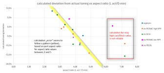
The tool/the formulas from the paper are not perfectly accurate (see #647), following some built speakers by augerpro and me. But the deviations seem to follow a pattern related to the length/diameter ratio. I would like to include the correction factor as well, but for that I would need more measured data ...
Also in my personal opinion the exact tuning is not that critical, considering the influence of room modes, speaker/listener placement, and tuning change with sound level change.
Very useful suggestion for his interesting site about port flares by @Collo in another thread:
https://www.subwoofer-builder.com/port-flares.htm
https://www.subwoofer-builder.com/port-flares.htm
Last edited:
Updated variable NFR port tuning frequency calculator
here is an update to the first beta version of an excel tool to calculate tuning frequency for fixed NFR=0.5 ports in post #616.
changes:
- variable user input NFR (normalized flare rate)
- provides the first longitudinal resonance frequency, as @Tenson proposed
- including correction factor based on evaluation of 14 built speakers by @augerpro and me. this result is only available for reliable Lact/Amin ratio range. the calculation based on the formula by salvatti/devantier/button is still available but will have higher inaccuracy (extimated +/- 15 %).
here is the as-built vs. salvatti-et-al formula evaluation graph I based the correction factor (yellow line) on:
general advice regarding the NFR value to chose:
- useful values are between 0,15 - 0,5. values below 0,2 are not very different from a simple tube with roundovers and I personally would rather use such a simpler port instead of the additional hassle with 3d-printing or bending port walls. in some cases with very long ports and high output however it might be a reasonable solution leading to reduced port length and good high level output.
- values above 0.5 tend to be very prone to turbulence inside the flare and have no real benefit.
- lower NFR value ports start compressing earlier but behave less critical with high outputs, even at low strouhal numbers below 1. There will be some noticeable noise at high levels.
- high NFR value ports (up to 0.5) don't compress at low levels and don't produce noise but output will collapse (very high compression) once a critical output level is exceeded, usually at strouhal numbers below 2. below the critical strouhal number (and above critical output level) the tuning of the speaker changes due to flow separation and there is very little useful output from the port, also affecting the loading of the driver and leading to higher driver excursion. there will also be strong low frequency noise. solving this problem is easy: just make the port surfaces (and length) bigger!
once more the NFR definition image by slavatti/denvantier/button (it's also included in the excel sheet):
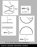
- salvatti proposed a NFR of 0.5 as ideal compromise.
- roozen proposed an ideal opening angle of 6° for each port wall and low roundover radius for high output ports, translating in a NFR of 0.105. but he also stated that for lower outputs (he mentioned 85 dB for his example) a higher curvature port will produce less blowing noises.
I will provide a comparison between passive radiator, NFR=0,5 port and NFR=0.2 port in the next postings!
as with the previous version the excel sheet is protected except user data fields just to avoid unintended changes, but there is no password protection, so feel free to unlock and change it!
Attachments
Last edited:
Attachments
lower NFR value ports start compressing earlier
I am probably missing something here. When I look at the Monacor data in post 704, on every graph, the low NFR port called “3D Big“ always looks like it produces less compression than higher NFR port “progr big” and the same comparing the two smaller versions.
I don’t understand how these graphs show any advantage for higher NFR. Any help appreciated.
Like I said, probably I am missing something.
You are absolutely right and there might be a problem with my simplified assumptions. Thanks for pointing this out!When I look at the Monacor data in post 704, on every graph, the low NFR port called “3D Big“ always looks like it produces less compression than higher NFR port “progr big” and the same comparing the two smaller versions.
The problem with my graphs is they suggests to compare port geometries as a "ranking" but in fact they don't.
The ports are very different in size and geometry and I used the graphs to look for correlations which (I think) I found.
According to my findings the limiting factor for the "progr big" port is it's small middle cross section in relation to the displacement (leading to low MPSN).
The lower NFR 3d_big port has a much wider middle cross section and is better in this case.
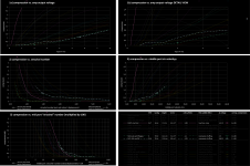
I took three ports, the two you mentioned and a third one ("BIG") and isolated the compression/input detail graph:
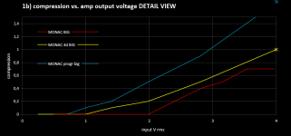
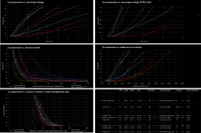
The "3d_big" and the "progr_big" port result in a tuning frequency of 34,5 Hz. At this frequency mainly the MPSN limits the "progr_big" port.
There indeed is no advantage in the low level area for the higher NFR port.
But if you look at the red "BIG" graph, this port resulting in a higher 50 Hz tuning (thus less critical for MPSN and in addition this port has a bigger middle cross section area) has NO compression at all at low levels.
This and the statements in the roozen and salvattiet al. papers is why I suggested that a higher NFR port has advantages for lower levels.
I'll keep this in mind for my further investigations!
Darn, I was actually hoping I just was reading the graphs incorrectly.
Salvatti et al. definitely have graphs of 3rd order distortion vs SPL for flared mouth ports which demonstrate a big advantage for increasing NFR below a critical SPL level.
On the other hand, Roozen argues (from his measurements and flow model) that ports that are gently tapered with an abrupt but rounded termination are superior, because flow separation when it occurs happens at a small edge, which radiates poorly and gives the port a near constant length.
Whereas, with flared mouth ports, flow separation occurs interior to the port with possibly worse consequences such as port tuning varying with intensity, and greater noise production.
I was hoping that your excellent larger set of data would definitively settle this disagreement which I will call the “flare” vs “taper” argument.
In practice we have restrictions, the port can only be so big in cross section and/or so big in length and these two approaches can give very different shapes.
I would appreciate any more thoughts people have on these issues
PR vs PORT
Here comes the the test speaker results with comparison between two passive radiators and two variants of ports.
See the attached PDF for detailled plans!
Some very general remarks:
- in order to get a sensible tuning I had to install two passive radiators, so the total PR Sd surface is very generous (driver 50 cm², PRs total 174 cm²), which gives an optimistic max output level.
- in order to install the vents in the same speaker and a similar position as the PRs I had to keep the vents rather short. This leads to low port mouth area and rather low strouhal numbers. For a really useful speaker with some safety headroom for the vents they would need to be bigger.
- when testing the PR version at high levels the entire enclosure was vibrating heavily and I had to stuff some additional pillows to avoid rattling. Air in a vent is only very loosely "attached" to the speaker but the PR vibration is directly transmitted to the enclosure and creates lots of vibration.
- the simulated PR helmholtz frequency was slightly higher than the actual one. I had already made the vents when doing the measurements, so the vented box is tuned slightly higher.
speaker with PRs positioned in a wall breakthrough for better isolation of dirver/PR/vent outputs (as shown in @Juhazi's thread):
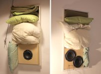
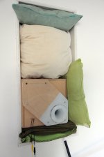
Same speaker but with an adapter board and one of the vent variants:
Vent variants, one with the bike-air-pump-absorber attached. The hole for the absorber was closed smoothly with clay for the non-absorber measurements.
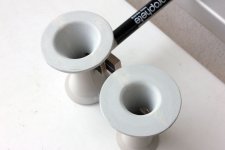
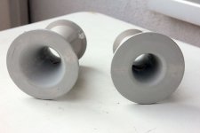
Both vents have the same length, but one has a NFR of 0,5 (more rounded shape) and the other one has a NFR of 0.2 (more straight).
I wanted to test whether my previous assumption of low NFR ports behaving better at low strouhal numbers is correct.
The low NFR port has a much smaller mouth diameter and area, thus will eventually compress earlier.
Impedance measurement:
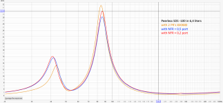
The PRs low impedance peak difference is interesting but probably not surprising, considering the PR system's higher order and steeper low rolloff.
also notable the slightly lower tuning of the PR version.
isolated port/PR responses:
see juhazi's thread for the driver output response.
For all measurements shown here I did not include any dampening material in the enclosure.
There is a disadvantage of the vents to be considered: the vent lenght and the enclosure width are very similar, thus the resonance effects add up.
The general output tendency is very clear:
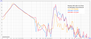
as to be expected the PR version is much less prone to enclosure resonance transmission. between 1-3 kHz the vents both transmit about 15 dB more rear speaker sound.
depending on the enclosure geometry and the port position and orientation these port/PR peaks will create peaks or dips in the total response.
All this high frequency output will be very much reduced by adsorption material in the enclosure. I would also say that for vented and PR speakers with output reaching the enclosure/vent resonance range there is no other sensible solution but a mass-loded TL system. see my tests here.
I then rotated the vents to the outside to be able to attach my variable resonance absorber (for this test still without latex membrane).
By the way: I first had a 1,5 cm absorber diameter, which did not provide useful results. widening the absorber diameter to 2 cm did the trick.
The absorber had the best effect at length setting of 6 cm (half the port length) and a 3 cm melamine foam piece stuffed all the way to the inside end.
here are the responses with absorbers and the PRs:
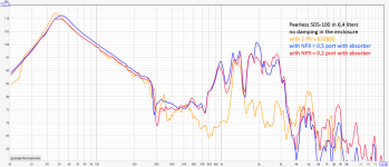
The main resonance is now similar to the PR (I suppose the absorber eats up the port's resonance effect). But there is still more resonant output from 800 Hz to 3 kHz than the PR version. The absorber even introduces a resonances at 1 kHz,
I guess with some absorber adjustment these results could be improved, but I would say it's better to just absorb the enclosure resonances and the back driver output by covering the enclosure interior with absorption material and ideally making it a MLTL.
Compression and distortion behaviour:
I made a hornresp simulation for all speakers and defined a useful maximum speaker input level of 8 V.
while more input voltage would be possible at the exact tuning frequency it would not make much sense, because once the frequency is slightly higher or lower the driver would quickly exceed it's Xmax.
I should also add that all my tests are done with rather small speakers and drivers to keep the expenses and the amount of work down!
measurements done with REW's real time analyzer.
X-axis always shows the amp output voltage.
compression:
The reference value for compression rate shown here is the lowest voltage (0,25 V rms) for all speaker variants.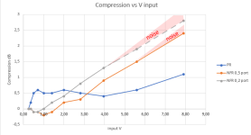
I already expected the PRs to be slightly less linear at low levels, but not so evidently!
Above 0,5 V the PRs are very constant up to the maximum level.
The ports have a slight "inverse" compression effect at low levels but then compression raises constantly. Up to 2,5/3 V the ports compress less than the PRs.
Both port start making audible wind noise above 1,5 dB of compression.
The NFR=0,2 port makes audible chuffing noise from 4 V up (strouhal number = 2,2 and MPSN = 30) with a slight chuffing peak at 1,4 kHz, the port's length resonance, but noise is still quite acceptable compared to sharp edge ports. The assumption that a low NFR port behaves better at low strouhal numbers was not confirmed. I suspect low NFR ports need a certain length to behave that way.
The NFR=0,5 port has no resonant chuffing behaviour but starts to make low frequency turbulent noise above 5,6 V (strouhal number = 1,5 MPSN =16), which is not very offensive, but clearly audible.
As I mentioned, for an actual speaker project I would make the ports bigger!
The nice thin is, that once the ports are just sligthly bigger all the adverse effects vanish immediately.
(strouhal numbers have a cubic relation to port diameter).
total distortion:
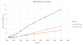
this is where the ports shine and the PR's show non-linear behaviour.
Most of the THD (no noise!) here is H2, so it's not very offensive.
While the ports show their limit by making wind noises, the PRs start to generate lots of harmonics.
I have to say that while the peerless PRs are well made they are incredibly cheap. More expensive PRs probably behave much better.
H3 distortion:
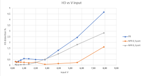
this is the revealing graph, because H3 is much more audible than H2 and can be quite disturbing.
This is where the advantage of the higher NFR port is evident and the correlation between H3 and noise is evident - at least for the high NFR port!
My first conclusion:
PRs do behave quite predictably and are not critical at high outputs. the resonance transmission is low and is probably no problem if there is some absorbing material in the box. Depending on the reference value for compression PRs don't compress at all or very little (at least for a generous total PR Sd).They do create significantly more harmonic distorsion.
Vents are more like little divas and need attention for correct placement, correct size and enclosure dampening. If done right they excel with low distorsion and good compression behaviour at low levels.
One more conclusion: the woofer installed in the wall provides incredible sound levels, even at just 8 V and a tiny 4" driver!
Attachments
Last edited:
I think these graphs also answer my questions and confusion when comparing your large set of data with the small sets of measurements that were available before.Vents are more like little divas and need attention for correct placement, correct size and enclosure dampening.
I like “ports are divas” and might add high NFR ports may be “Goldilocks“. I think that you have proven that there is a convenient “Goldilocks zone“ in diameter (or Strouhal number) where higher NFR is superior. I see this in the last graph above. At both extremes it looks like low NFR might measure better, but in the designed range of sound levels, higher NFR is clearly better.
Thanks again for all of this work you have done, and patience with my interruption.
I think I found the relevant factor for different optimal geometries as found by Roozen and Salvatti et al.I would appreciate any more thoughts people have on these issues
It's in fact quite obvious, but you had to beat me to it!
Thanks for that!
Roozen has tested long ports for a small woofer and a small enclosure.
Length is not provided in the paper, but the main resonance is said to be at 1100 Hz. That translates to a lenght of 15 cm.
Min. port diameters vary between 1,6 to 2,1 cm,
Thus a Length/Dmin ratio between 7,2 and 9,6.
Salvatti et al provided the port length with 120 mm and differing min. diameters between 58 and 69 mm.
Thus a Length/Dmin ratio between 1,75 - 2,05.
this is in accordance with my findings, that long ports are less dependent on low strouhal numbers.
The long straight, uninterrupted air flow in a long port can stay laminar even with some turbulence at the ends.
Short ports are very much influenced by the turbulent or laminar airflow at the ends.
Very short ports have no straight flow section at all.
I even mentioned this dependency on length/Dmin ratio in my data collection posting:
A) Low MPSN influence ports
compression starts very sudden at a MPSN<20.
All these ports are long in relation to their minimum diameter. (L/Dmin > 6).
As I undestand the long port will provide a very steady laminar airflow, even for high displacements at the narrow port throat.
The flow is not disturbed by turbulent flow coming from the (flared) port ends.
The "big 3d" port shows that a low flare rate port will work fine even with very low strouhal numbers (as stated in the roozen paper, by the way).
B) Normal MPSN influence ports
compression starts slightly more gradual with MPSN between 30 and 40.
A light correlation to the strouhal number graph is evident for these ports.
most ports have a length/min-diameter ratio of 3-5. only exception is the rounded hole for the SONY woofer with a L/Dmin ratio of 0,53.
In my opoinion it is generally not advisable to make very short ports (hole in the box), because the laminar flow cannot build up.
C) Strong MPSN influence ports
compression starts at high MPSN above 50.
these ports have a similar L/Dmin-ratio of 3-4,5 but a high tuning frequency and/or very small throats.
There might be other influences that lead to this behaviour and maybe I will close this group once I know more about it!
Not at all!and patience with my interruption.
I am really glad you mentioned this! Thanks again!
So, very simplified:
Wide diameter/short ports need a higher NFR. Salvatti found ideal NFR = 0,5.
Narrow diameter/long ports need a lower NFR. Roozen found ideal exit angle of 6° at each side, translating to a NFR = 0,1.
Last edited:
When I read that paper, I was not so convinced by his argument that NFR = 0.5 is an “optimum” value. His distortion graphs get lower and lower as NFR increases all the way to 1. On the downside, the higher NFR ports overload a little more easily as one would expect.Wide diameter/short ports need a higher NFR. Salvatti found ideal NFR = 0,5
I get the impression that he somewhat arbitrarily chose NFR = 0.5 as a compromise. I was wandering what you think about NFR > 0.5
yes, it's a compromise or an overall good/acceptable solution.he somewhat arbitrarily chose NFR = 0.5 as a compromise.
I observed that for higher NFR values the tendency for low frequency turbulent airflow/flow separation increases significantly.
So even if the already very low distortion numbers decrease further the port gets either very big or is not able to produce high levels.
With such high curvature there is less probability for a controlled laminar airflow.
Or, in other words, the middle port section gets so small that it will lead to high velocities/displacement and boundary layer turbulence (high MPSN).
See the very small NFR ~ 1 port here and measurements in the following posts.
I also think that distortion of port/PR output should not be overrated. Distortion is not very audible at low frequencies and it only affects a very tiny range of the whole spectrum.
I can also tell you from my listening and testing experience if I have to chose between a bit of distortion or a bit of chuffing noise I would definitely rather accept distortion.
Last edited:
By the way - my speaker with two passive radiators would of course be perfectly suited for force cancelling side firing PRs!but the PR vibration is directly transmitted to the enclosure and creates lots of vibration.
Influence of dampening material in the box
I "lined" the same test speaker (see #753) with two 12cm wide, 40 cm long strips of egg-crate foam positioned at the side panels and a piece of wadded natural wool (or cotton?) fleece on the bottom of the speaker.The speaker is far from being filled up with dampening material to avoid absorbing the useful bass energy and the dampening of the enclosure could of course be optimized further.
Here are the responses without dampening material in the enclosure for the PR, the NFR=0.5 port without absorber tube and the same port with absorber tube (6 cm extension air pump with 3 cm basotect):
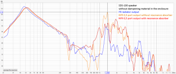
and here are the corresponding responses with dampening material in the box:
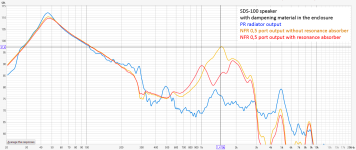
as I mentioned before the best solution would be to include a lined stiffening board between driver and ports/PR in the enclosure and turn the speaker into a MLTL. The layout and TL development can be simulated and optimized e.g. with hornresp.
By the way, does anybody know what causes the even PR/port output slope to suddently plummet at about 300 Hz?
I cannot replicate it with hornresp simulations.
Is this related to enclosure dimensions? or distance between driver and PR/port (which is not the same for PR and port, by the way)?
Last edited:
Hi,Updated variable NFR port tuning frequency calculator
here is an update to the first beta version of an excel tool to calculate tuning frequency for fixed NFR=0.5 ports in post #616.
changes:
- variable user input NFR (normalized flare rate)
- provides the first longitudinal resonance frequency, as @Tenson proposed
- including correction factor based on evaluation of 14 built speakers by @augerpro and me. this result is only available for reliable Lact/Amin ratio range. the calculation based on the formula by salvatti/devantier/button is still available but will have higher inaccuracy (extimated +/- 15 %).
here is the as-built vs. salvatti-et-al formula evaluation graph I based the correction factor (yellow line) on:
View attachment 1348446
general advice regarding the NFR value to chose:
- useful values are between 0,15 - 0,5. values below 0,2 are not very different from a simple tube with roundovers and I personally would rather use such a simpler port instead of the additional hassle with 3d-printing or bending port walls. in some cases with very long ports and high output however it might be a reasonable solution leading to reduced port length and good high level output.
- values above 0.5 tend to be very prone to turbulence inside the flare and have no real benefit.
- lower NFR value ports start compressing earlier but behave less critical with high outputs, even at low strouhal numbers below 1. There will be some noticeable noise at high levels.
- high NFR value ports (up to 0.5) don't compress at low levels and don't produce noise but output will collapse (very high compression) once a critical output level is exceeded, usually at strouhal numbers below 2. below the critical strouhal number (and above critical output level) the tuning of the speaker changes due to flow separation and there is very little useful output from the port, also affecting the loading of the driver and leading to higher driver excursion. there will also be strong low frequency noise. solving this problem is easy: just make the port surfaces (and length) bigger!
once more the NFR definition image by slavatti/denvantier/button (it's also included in the excel sheet):
View attachment 1348450
- salvatti proposed a NFR of 0.5 as ideal compromise.
- roozen proposed an ideal opening angle of 6° for each port wall and low roundover radius for high output ports, translating in a NFR of 0.105. but he also stated that for lower outputs (he mentioned 85 dB for his example) a higher curvature port will produce less blowing noises.
I will provide a comparison between passive radiator, NFR=0,5 port and NFR=0.2 port in the next postings!
as with the previous version the excel sheet is protected except user data fields just to avoid unintended changes, but there is no password protection, so feel free to unlock and change it!
salvatti / devatier / button proposed formula to calculate effective length with NFR, Leff = Lact + Dmin, is problematic with very low NFR. As NFR goes toward zero the port approaches shape of just regular tube, but calculated effective length goes up. Logically Leff should approach the Lact when NFR goes toward 0, shouldn't it?
So, Leff could be something like Leff = Lact + Dmin * c * NFR? c would be some correcting factor. c = 2 would give the original proposed formula with NFR 0.5.
I do not know if this would correlate the data anymore though, but it doesn't seem logical to add extra length from nothing either.
Last edited:
- Home
- Loudspeakers
- Multi-Way
- Investigating port resonance absorbers and port geometries

