Hello all,
I've got a Zapco 9.0XD that powers up (green LED) for 5 seconds then when the volume light (yellow led) flashes, relay clicks in, then the protect led flashes then the #2 and #4 pre-clip leds illuminate and stay illuminated while the amp continues drawing excessive current as can be seen by the head lamp in series with B+.
This amp is supposed to idle at 3.8 amps so I placed a 10 amp fuse inline with B+ while removing the headlamp and it blew it as soon as the relay clicked.
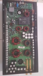
Upon visual inspection nothing looks bad, except the 30 ohm 3 watt resistor R136 in the power supply looks discolored/burned, but still reads 29.87 ohms.
I am going to start removing the clips and testing FETs, Transistors and diodes, but if anybody is familiar with this one and could point me in the right direction of where to start troubleshooting I would greatly appreciate it.
Also, of course it would be great if someone had a schematic.
I have an email and phone number for Zapco and plan on contacting them Tuesday if no one has a schematic, but I am not sure how they are about releasing that info.
I can also supply pictures of more specific areas of the board.
Thanks.
I've got a Zapco 9.0XD that powers up (green LED) for 5 seconds then when the volume light (yellow led) flashes, relay clicks in, then the protect led flashes then the #2 and #4 pre-clip leds illuminate and stay illuminated while the amp continues drawing excessive current as can be seen by the head lamp in series with B+.
This amp is supposed to idle at 3.8 amps so I placed a 10 amp fuse inline with B+ while removing the headlamp and it blew it as soon as the relay clicked.
Upon visual inspection nothing looks bad, except the 30 ohm 3 watt resistor R136 in the power supply looks discolored/burned, but still reads 29.87 ohms.
I am going to start removing the clips and testing FETs, Transistors and diodes, but if anybody is familiar with this one and could point me in the right direction of where to start troubleshooting I would greatly appreciate it.
Also, of course it would be great if someone had a schematic.
I have an email and phone number for Zapco and plan on contacting them Tuesday if no one has a schematic, but I am not sure how they are about releasing that info.
I can also supply pictures of more specific areas of the board.
Thanks.
Attachments
Last edited:
I didn't find anything useful.
Is the relay in series with the speaker output?
If so, without a load, I don't know what could have made the fuse blow unless there is some type of circuit between the relay and the speaker terminals.
Could there be a strand of wire across the terminals, themselves?
Is the relay in series with the speaker output?
If so, without a load, I don't know what could have made the fuse blow unless there is some type of circuit between the relay and the speaker terminals.
Could there be a strand of wire across the terminals, themselves?
I moved the sister board on the input side of the amp out of the way and found a ball of solder across two smd resistors. This allowed the amp to stay partially running but the protection light was still on.
The amp then shut completely off and put my power supply into protect. I disconnected the power supply, checked continuity between B+ and Neg and had 0.5 ohms.
Checked again a few minutes later and B+ to Neg read 70 ohms and then counted up, like charging a capacitor/capacitors, and settled at 5.5 M ohms.
I took the pcb out of the case/sink to check the bottom of the board for shorts between B+ and neg and didn't see anything. The board wont power up out of the sink, I am thinking it uses the bolts that mount the pcb to the sink as a ground, but not sure.
One more thing I should mention, earlier I referenced a relay kicking in. That was incorrect, there is no relay, I am not sure what I could hear clicking, but upon moving the input board out of the way, there is no relay.
Last edited:
There seems to be similarities but different devices.
What area/components, to start, should I check/trace that would be helpful or better determine how similar they are?
As far as the mounting holes in the pcb, I think they are using the case to supply a ground to the output side of the pcb. I jumped from one mounting hole to the other and the amplifier will start but still goes into protect. Without the jumper the amp will do nothing.
Not sure if this helps, but here are some of the components used:
FETs:
17 pcs IRFZ46Ns (P.S. ?)
2 pcs P16NE (P.S. ?)
8 pcs W34NB20 (outputs ?)
Rectifiers:
8 pcs MUR1540s
Regulators:
1 pcs 7812
LM431
Drivers:
6717A, 6727A, MPSA56
I.C.s: (Just a few)
SG3525A
4560
3843A
NEC2701
ATMEGA103
TA0140A
When the amp wouldn't start, I was looking for some place to start, like the voltage on the PS driver IC.
Now that it's powering up, confirm that the outputs have pulldown resistors and if so, pull the tripath module (assuming that it's in a socket). Does the amp still go into protect?
Now that it's powering up, confirm that the outputs have pulldown resistors and if so, pull the tripath module (assuming that it's in a socket). Does the amp still go into protect?
When it wouldn't start, when it was in the sink, that was when B+ and Neg were shorted, for some reason that condition has changed.
Yes 5.6 ohm gate resistors.
It still does the same thing with the T0104a removed.
On power up:
It starts for about 2 seconds with green led on, tries to pull high current for a second then clicks and goes through the same process once more.
Then pre-clip led flashes, volume led illuminates, protect led flashes 4 times then remains solid. The green led stays on with the protect led.
Checking the MUR1540s, IRFZ46Ns, and W34NB20s I found no shorted junctions.
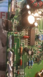
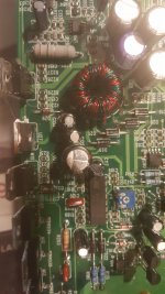
Checking the diodes on the pcb the only one I could find that appears shorted is D32 in the pic below.
I am not sure but it appears to be in parallel with L14 the 100 uH inductor and is also connected to the gate of M10 ( P16NE)
Checking the diodes on the pcb the only one I could find that appears shorted is D32 in the pic below.
I am not sure but it appears to be in parallel with L14 the 100 uH inductor and is also connected to the gate of M10 ( P16NE)
Attachments
The 'pulldown' resistors are what R24 and R25 are in the clarion diagram. They keep the gate from charging when the drive circuit is open.
Desolder one terminal of the inductor to see if the diode still appears to be shorted.
Desolder one terminal of the inductor to see if the diode still appears to be shorted.
It does have the 20K pull down resistors. OK, thanks.
The diode checks fine.
I put my scope probe on the gate of one PS FET while powering up. It is trying to build a square wave for a second before it goes into protect.
The diode checks fine.
I put my scope probe on the gate of one PS FET while powering up. It is trying to build a square wave for a second before it goes into protect.
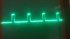
I also noticed while in protect, one IRFZ46N (M9) with it's drain connected the toroid (T1), has a square wave visible on it.
Scope set to 10 V/Div and 5 uS
Where should I go from here?
Scope set to 10 V/Div and 5 uS
Where should I go from here?
Attachments

It looks like pin 6 of the 3843A is driving the gate of M9.
Also pin 4 has a sawtooth wave ~ 1.5 Vpp
It appears that M9 is the only FET driving T1.
Please bear in mind that this is a 4 layer pcb with a lot of components and no way to see the inner layers so I may be leaving some connections out, but I am being as thorough as I can.
I used my scope to trace the signal for the gate of M9 and while looking around I noticed that the ATmega103 was doing something on several pins. The crystal oscillator X3 connected to it had a "sinewave" on it.
Last edited:
I'm not sure what the question is, concerning the small transformer.
How does the signal on the drain of M9 vary (from what you posted) before the amp goes into protect?
If the amp acts the same with or without the module in it, I'd troubleshoot with it out of the amp to prevent possibly damaging it.
If it's drawing excessive current when the amp tries to power up, what FETs are heating up?
What do you consider to be 'excessive'?
Are you using a B+ limiter of some sort?
Hello,
I didn't have a question about the transformer, I mentioned that area only because it was the only area I could find a sign of life when the amp was in protect and I thought it might help you help me. I think it is the secondary supply, because it also goes to the 7812 and has a positive and negative component to it on the diodes connected to the other side of the transformer.
It doesn't really change, it flickers a little as the amp goes into protect.
No FETs are heating up, it only does it for a fraction of a second before it shuts down.
Well, right know it is able to attempt to start on a 10 amp fuse inline, so now not to bad, my meter jumped to 8 amps for a split second before the amp went into protect.
I was using a headlamp earlier and I could tell it was pulling "excessive" amps, because the headlamp gave me a "sunburn".🙂 (very bright)
I then tried a 10 amp fuse and blew it instantly. I then tried a 15 amp fuse, blew it instantly. Powered up with no fuse and put my 40 amp supply into protect.
At this point, like I mentioned before checked continuity between B+ and Neg and was 0.5 ohms. That has somehow changed now and B+ to Neg starts at 70 ohms and counts up to 5.6 M ohms.
The reason I thought that the current draw had something to with it, because upon start-up it with the headlamp in series, it powers up for a second, then a bright flash from the headlamp, then the amplifier instantly goes into protect following the bright flash from the headlamp. The amp goes into protect within 3 seconds of attempting to start up.
What happened between
'right know it is able to attempt to start on a 10 amp fuse inline'
and
'put my 40 amp supply into protect'?
'right know it is able to attempt to start on a 10 amp fuse inline'
and
'put my 40 amp supply into protect'?
- Home
- General Interest
- Car Audio
- Zapco C2K 9.0XD