Your Mofo boards look equally as stunning 😀 (had a few made while I was at it)
Thanks for sharing as always!
Thanks for sharing as always!
Attachments


Last edited:
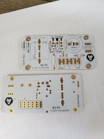
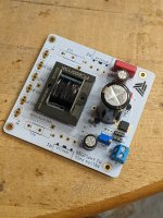
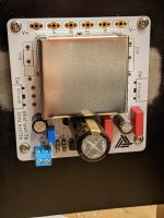
I just got the boards and they turned out nice. TEKO cover fits nicely
80mmx80mm mounting version
PM if you would like a pair (I have enough for 15 or so amps)
Hi Guiness,
Your boards look cool! Where did you source the TEKO shield from?
Hi Prasi!
I love the compactness and use of SMD components in your layout, Bravo!!
Nice Artwork 🙂
Looks super Guiness! Thank you for the care package! It will look great with my white SLB boards!!
Best,
Anand.
Best,
Anand.
Any interest in Europe to produce couple of those PCBs?
Or someone have them to sell me a pair?
me too
please PM
thx
chris
TME had the TEKO covers, shipping was incredibly fast. Less than 48hrs to NY, USA.
hmmm..
if i search with 3710.6 at reichelt and conrad i always get a smaller one = 50x54x19mm😕
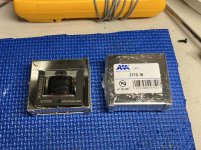
Its exactly the part you need for this pcb. 54x50x19 mm height.
3710.16 TEKO - Enclosure: shielding | X: 50mm; Y: 54mm; Z: 19mm; steel; Series: PBC | TME - Electronic components
3710.16 TEKO - Enclosure: shielding | X: 50mm; Y: 54mm; Z: 19mm; steel; Series: PBC | TME - Electronic components
THX prasi!
this made me confused..
just got the boards and they turned out nice. TEKO cover fits nicely
80mmx80mm mounting version
this made me confused..
just got the boards and they turned out nice. TEKO cover fits nicely
80mmx80mm mounting version
TME had the TEKO covers, shipping was incredibly fast. Less than 48hrs to NY, USA.
Vunce,
Did you order just the TEKO covers or more stuff? Was there a minimum order requirement?
Best,
Anand.
Hi Anand,
No minimum amount, items totaled $25, shipping was $10.
I’m still amazed how fast I received the order. TME is Faster than ordering parts locally!!
These are nice little shields, solid construction.
Enjoy your weekend!

No minimum amount, items totaled $25, shipping was $10.
I’m still amazed how fast I received the order. TME is Faster than ordering parts locally!!
These are nice little shields, solid construction.
Enjoy your weekend!
A while ago, there was another compact PCB for the M2 that takes the TEKO cover as well.
I built my M2 on those boards - they are very good quality boards, easy to solder, nice and easy to build on them, and resulted in a compact M2.
You could also cascode the JFETs on these boards.
The board was done by member JPS64 - you can check with him, maybe he has still some boards left. They are "DIY-NR003".
My first GB
Regards, Claas
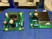
Some photos of progress
Hi All,
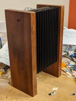
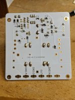
I've been soldering away, and I thought I'd post some photos. I am reusing heatsinks with hardwood sides that used to have a p2p F5 in them, one is shown in the first photo. Power supply will be a separate unit, attached via umbilicals. I have to pause while I wait on some parts that were out of stock (R13 and R14), but plenty to do getting the PSU done.
The shield came from TME amazingly quickly. I can't believe things arrive faster from Poland than from other parts of the US. Fits beautifully, too.
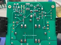
I have a question. Possibly a silly one. The white boards really make the excess flux stand out. Isopropyl alcohol gets it off just fine, but it occurred to me that I don't know if any components on boards might be vulnerable to it. Years ago shellac was used in transformers, for instance, and alcohol would mess that up fast. It seems unlikely that modern transformers still use shellac, but are there any components that you should be careful about? Not just on this project, but at all? Or can you just drop completed boards in a bath of the stuff?
Hi All,
I've been soldering away, and I thought I'd post some photos. I am reusing heatsinks with hardwood sides that used to have a p2p F5 in them, one is shown in the first photo. Power supply will be a separate unit, attached via umbilicals. I have to pause while I wait on some parts that were out of stock (R13 and R14), but plenty to do getting the PSU done.
The shield came from TME amazingly quickly. I can't believe things arrive faster from Poland than from other parts of the US. Fits beautifully, too.
I have a question. Possibly a silly one. The white boards really make the excess flux stand out. Isopropyl alcohol gets it off just fine, but it occurred to me that I don't know if any components on boards might be vulnerable to it. Years ago shellac was used in transformers, for instance, and alcohol would mess that up fast. It seems unlikely that modern transformers still use shellac, but are there any components that you should be careful about? Not just on this project, but at all? Or can you just drop completed boards in a bath of the stuff?
Attachments

njepitt,
Are you using at least some liquid flux prior to soldering the components? It would make life easier and you won't have to use an excess of solder. This is particularly important with SMD components. In fact, with SMD, I use a liquid solder pen. I also don't solder SMD and some thru hole components without a Yoctosun headlamp or equivalent.
Whether thru hole or SMD, some of these PCB's are quite thick and need a soldering iron and soldering tip with good thermal capacity, but flux certainly helps tremendously. One can wait a very long time waiting for the component leads to heat up! Especially with large electrolytics or binding posts!
In order to remove excess flux, I have a 4 step plan that works every time.
1. Wash excess flux along with an ESD brush (looks like a tooth brush and available on Amazon) using Chemtronics Flux-Off. This gets all the flux removed but leaves some residue. There are cheaper places that sell it, so shop around.
2. Immediately pour distilled water on the board, gently shaking off the excess water. I get my distilled water from our grocery store. $1/gallon.
3. Place the board on a wooden lazy susan or equivalent, and use your hot air gun while spinning the lazy susan and gently drying the board. The board should be fully dry in 5 minutes. Keep a good distance from the PCB so you don't fry components, capacitors, etc...the lazy susan helps here!
4. Remove any excess flux/residue remaining with little sprays of the Chemtronics Flux Off and dab it with Kim Wipes.
Best,
Anand.
Last edited:
Hi Anand,
No, I don't usually use liquid flux. I've never felt the need, although having said that my SMD solder joints don't always look as nice as other people's and that solder pen looks very cool, and would definitely help with SMD, so I'll give it a try. Thanks for the suggestion.
Your procedure for cleaning flux off sounds very effective, but I'd still like know the answer to my question about isopropyl alcohol.
Best
Nigel
Nice progress njepitt!
I’m with you, I was blown away how quickly I received the TEKO shields.
Sockets for the JFET’s, good idea 😉
Good advice Anand 🙂
I’m with you, I was blown away how quickly I received the TEKO shields.
Sockets for the JFET’s, good idea 😉
Good advice Anand 🙂
Nigel,
I don't have an exact answer, but I do know that isopropyl alcohol is a mildly aggressive flux cleaner compared to even the Chemtronics which cannot even ship by air due to the flammability. Neurochrome's website has a "Choosing Solder" section with a good discussion on solder, importance of flux in soldering electronics, and also removal of said flux. Since the Chemtronics is moderately aggressive, I don't directly apply it to areas with ink print, for example the labels of electrolytic capacitors as it fades. This doesn't happen when I use isopropyl alcohol however. And yes, I have literally poured isopropyl alcohol on these finished boards. The only problem is that it doesn't get the toughest of flux residues without some aggressive brushing. That being said, I have never destroyed any passive or active parts using isopropyl alcohol. I would surmise that isopropyl alcohol for cleaning purposes is fairly safe. No experience directly on transformers though. I usually just clean the leads as I have never applied any flux to the external aspects of the transformer nor had a need to do so.
With transformers like the Edcor in the M2, I am just careful about not directly spraying/pouring any of these corrosive cleaners directly into the body of the transformer. Usually, I solder all the small passives first, then clean. Then large capacitors and then a gentle clean. Finally, I would solder the transformer and MOSFETs last so there will not be a need to pour any cleaners/solvents, and just dab a little of the cleaner here and there to remove the excess flux from the MOSFET pins and transformer pins.
I have seen multiple designers recommend isopropyl alcohol with little warnings or reservations on their pcb designs.
Best,
Anand.
Last edited:
Nigel,
Your progress update motivated me to complete the throught hole parts on my pair of M2’s. They are ready for all the FET’s and heatsink mounting. That is the issue at hand, still looking for a suitable and pleasant looking chassis.
For power supply, I can go down two different paths, linear supply based on the SLB psu or an SMPS from Cresnet (Micro-Audio) designed for Class A amplifiers.
Much experimenting in the near future 🙂
What do you plan for your PSU?
Attachments
Last edited:
Attachments
- Home
- Amplifiers
- Pass Labs
- Nelson Pass M2