Hi,
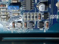
Got in a crossfire vr4000d in protect. No shorted FETs, I’m working through the power supply I found some shorted drivers. I can’t seem to find info on these, anyone got correct numbers, or subs?
DY 411
Got in a crossfire vr4000d in protect. No shorted FETs, I’m working through the power supply I found some shorted drivers. I can’t seem to find info on these, anyone got correct numbers, or subs?
DY 411
Attachments
Thanks perry!
I got the drivers sorted, and moved along troubleshooting.
Testing the voltages on the output of the 339, I found pin 2 was ‘high’ it measured 2.21v.
Looking at the inputs, I have 4.81v on pin 4 and 5.01v on pin 5. If I short pins 4 and 5 together I get the amp to power up.
Pins 5 and 6 are tied together so they should be the reference side. Im following the circuit through the components But they appear at first testing to be ok.
Any suggestions?
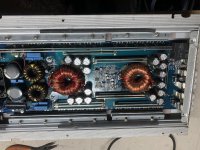
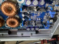
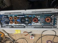
Post a photo of the component side of the entire main board and the component side of any driver boards.
I did a search, but not much info on these amps. The driver boards have the DIl4060 chips.
Attachments

What's the B+ voltage into the amp?
What happens if you move the high-voltage jumper to the other position?
What happens if you move the high-voltage jumper to the other position?
I have the B+ set at 11.8v.
I tried the high voltage jumper in the off position and the amp remains in protect.
I tried the short circuit protection jumper in the off position also,,amp remains in protect.
I tried the high voltage jumper in the off position and the amp remains in protect.
I tried the short circuit protection jumper in the off position also,,amp remains in protect.
I tried it at 13, amp still in protect.
I shorted pins 3 and 4 on the 339, protect light came off, current went up to 7 amps on the power supply.
I shorted pins 3 and 4 on the 339, protect light came off, current went up to 7 amps on the power supply.
Did you see the expected change in the voltages on the points that you believed were the high/low voltage protection when you increased the DC input voltage?
Is 7 amps excessive for this amp?
If you force the amp out of protection, does it work perfectly?
2.2v output on the LM339 is odd. They are typically going to be at 0v or at the supply/regulated voltage.
If you force the amp out of protection, does it work perfectly?
2.2v output on the LM339 is odd. They are typically going to be at 0v or at the supply/regulated voltage.
I believe 7 amps is excessive at this point with protection on.
- I don’t have a gate drive signal coming out the 494,
- I don’t have a sawtooth on pin 5 of the 494,
- I have reference 5v on pins 13,14,15
If short I pins 4 and 5 of the 339:
- the protect light goes off,
- the transformers begin to get warm a bit,
- the sawtooth comes up at pin 5 of the 494,
- I measured a faint 1.92v with the scope at the FET gate.
I measured the dc voltages of both chips:
494
1. 0.021
2 4.920
3. 0.058
4. 3.070
5. 1.450
6. 3.631
7. 0.002
8. 11.02
9. 0.930
10. 0.131
11. 10.99
12. 10.99
13. 4.92
14. 4.92
15. 4.92
16. 0.015
339:
1. 0.112
2. 0.705
3. 11.34
4. 5.574
5. 4.742
6. 4.742
7. 3.360
8. 4.34
9. 2.329
10. 0.042
11. 0.002
12. 0.002
13. 0.038
14. 0.113
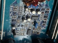
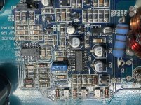
I’ve attached a pic of the PS control Section, it seems pin 3 of the 494 is not connected/being used as an input.
Looking back at the dc voltages of the 339 it seems I have other faults.
When the amp came in it had c31 blown apart. I believe this to be a snubber on the secondary side of the transformer and not affect the troubleshooting, I have not sourced or replaced this to this point.
- I don’t have a gate drive signal coming out the 494,
- I don’t have a sawtooth on pin 5 of the 494,
- I have reference 5v on pins 13,14,15
If short I pins 4 and 5 of the 339:
- the protect light goes off,
- the transformers begin to get warm a bit,
- the sawtooth comes up at pin 5 of the 494,
- I measured a faint 1.92v with the scope at the FET gate.
I measured the dc voltages of both chips:
494
1. 0.021
2 4.920
3. 0.058
4. 3.070
5. 1.450
6. 3.631
7. 0.002
8. 11.02
9. 0.930
10. 0.131
11. 10.99
12. 10.99
13. 4.92
14. 4.92
15. 4.92
16. 0.015
339:
1. 0.112
2. 0.705
3. 11.34
4. 5.574
5. 4.742
6. 4.742
7. 3.360
8. 4.34
9. 2.329
10. 0.042
11. 0.002
12. 0.002
13. 0.038
14. 0.113
I’ve attached a pic of the PS control Section, it seems pin 3 of the 494 is not connected/being used as an input.
Looking back at the dc voltages of the 339 it seems I have other faults.
When the amp came in it had c31 blown apart. I believe this to be a snubber on the secondary side of the transformer and not affect the troubleshooting, I have not sourced or replaced this to this point.
Attachments


If you have 5v on pin 14, you must have a sawtooth on pin 5, regardless whether the amp is in protect or not.recheck.
The scope waveform is useless without the timebase.
Are you saying that the amp was drawing 7 amps without any drive signal?
The scope waveform is useless without the timebase.
Are you saying that the amp was drawing 7 amps without any drive signal?
If you had no sawtooth with 5v on 14, I'd suspect either the 494 or one of the timing components.
Arite, I swapped out the timing cap and the 494. I have the sawtooth on pin 5 but still no waveforms on 9 and 10.
The output on terminals 9 and 10 depends on the voltage on the other terminals. Post the voltage on 1-4, 15 and 16, at least.
Hold on, I think I have something happening on the drive circuitry. With pin 9 and 10 out the circuit, I have square waves.
Reviewing pins 1 and 2, I should be getting output, I lifted 9 and 10 and I have square waves on both.
Do you know of other replacements for the DY 411? I got some surface mount diodes around those transistors, they’re testing good but Incase I do find something.
Reviewing pins 1 and 2, I should be getting output, I lifted 9 and 10 and I have square waves on both.
Do you know of other replacements for the DY 411? I got some surface mount diodes around those transistors, they’re testing good but Incase I do find something.
- Home
- General Interest
- Car Audio
- Crossfire vr4000d