I have built an audio amp based on a Bob Cordell triple stage design.
During testing the one channel worked well with a sine wave input and just an oscilloscope on the output. However when I connected a speaker to it there was a severe parasitic oscillation on the output. Also the heat sink got really hot very quickly.
When I tested the second channel all I could see was parasitic oscillation when only the oscilloscope was connected.
I tried connecting a power supply to both units and only got parasitic oscillation on both outputs.
I have since found that the triple output design can suffer from this fault depending on layout.
Any advice?
I had similar trouble with irfp240 irfp9240 and tried ferrite beads on gate, and also rail capacitors as close as possible.
Does it oscillate with shorted input and no load?
Does it oscillate with shorted input and no load?
Its the schematic on page 65 of the book power amplifier design.
I built this amp as a replacement for the base amp on my triamp unit as the existing base amp is built on a now obsolete chip driver.
I built this amp as a replacement for the base amp on my triamp unit as the existing base amp is built on a now obsolete chip driver.
If I were you I would try and rule out pcb oscillation, put a 100 nf cap on source pins and then to ground.
Its fig 3.10 showing output stage with triple emitter follower.
Due you mean the signal input when you say source pins?
Due you mean the signal input when you say source pins?
I mean try see if it oscillates with shorted input and no load connected, if it still oscillates the try 100nf on source pin to rule out pcb parasitic,
If it still oscillates with 100nf you could make an rc across source/drain 100nf 47ohm.
If it still oscillates with 100nf you could make an rc across source/drain 100nf 47ohm.
a schematic for those who wish to help but don't have the book handy would be helpful.
that being said, a couple of things to check for:
if it is all BJTs, do you have small resistors (10ohms or less) at the base of outputs and drivers?
if it uses MOSFET outputs, do you have large enough gate resistors?
and are those gate or base resistors very close (with short paths) to their respective devices?
do you have decoupling caps of "appropriate" value placed "correctly" with short ground paths?
are you using long leads to connect the source to the input?
are you using long leads to connect the load?
do you have the R-C network on the output? (I'm guessing not - I think you would smell the resistor getting warm with parasitic oscillations!)
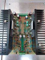
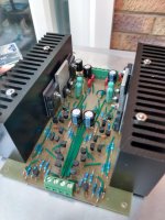
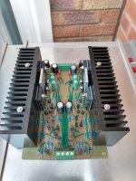
schematic and complete pictures of your setup (so we could see the wiring and gauge distances) would help!
so would scope pictures of the oscillations; the frequency would provide some additional clues...
good luck!
mlloyd1
that being said, a couple of things to check for:
if it is all BJTs, do you have small resistors (10ohms or less) at the base of outputs and drivers?
if it uses MOSFET outputs, do you have large enough gate resistors?
and are those gate or base resistors very close (with short paths) to their respective devices?
do you have decoupling caps of "appropriate" value placed "correctly" with short ground paths?
are you using long leads to connect the source to the input?
are you using long leads to connect the load?
do you have the R-C network on the output? (I'm guessing not - I think you would smell the resistor getting warm with parasitic oscillations!)
schematic and complete pictures of your setup (so we could see the wiring and gauge distances) would help!
so would scope pictures of the oscillations; the frequency would provide some additional clues...
good luck!
mlloyd1
Well put, wasn't able to find the schematics in question, lots can cause it cable dressing cable length etc etc pictures/schematics needed.
The book can be downloaded as pdf for free, even so I don't want to put schematic online due to copyright.
Output transistors are MJL21193/MJL21194 BJT's
Only have 10R resistor plus 100n cap at output.
About .5m lead on input.
3m lead on output.
No decoupling caps.
Will try and get suitable photos
Output transistors are MJL21193/MJL21194 BJT's
Only have 10R resistor plus 100n cap at output.
About .5m lead on input.
3m lead on output.
No decoupling caps.
Will try and get suitable photos
If it's for free download, no copyright violation, and my humble opinion is that if any member here who needs help he/she must go an extra yard and provide schematics and pics in first post.
Could it be that the speakers loading the output causes it to have insufficient dampening, and causes there to be stray capacitance or inductance where it wasn't supposed to be?
I am quite certain that the "free PDF download" you mention IS a copyright violation.The book can be downloaded as pdf for free, even so I don't want to put schematic online due to copyright.
That said, MAYBE a cropped, incomplete section of said schematic, showing only the relevant parts, say output transistors, Zobel/inductor (if appliccable) and NFB network COULD be acceptable or fair use for specific Servicing purpose.
Not sure what Moderators say in that specific case.
Of course, please post YOUR pictures of the build.
I trust the circuit itself is fine, but actual implementation is anybody´s guess.
Its a bit late now, but that was what I thought so was hesitant to put the circuit online.
Not sure if it can be removed.
Not sure if it can be removed.
Last edited:
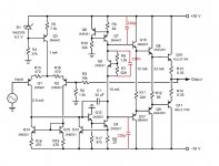
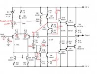
This is more complete amp circuit and I built my amp like this before with no oscillation.
Attachments
Last edited:
Q13 is for protection purpose and for diy no need to use it and since the driver using a relative high driving current and the sounding will be expected good.
Last edited:
- Home
- Amplifiers
- Solid State
- Parasitic Oscillation