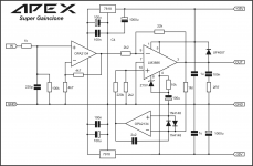
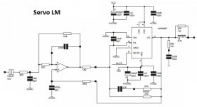
Hi Friends,
will Super Gainclone with OPA2132 work ?
OPA2132 and OPA2134 - Amplifiers forum - Amplifiers - TI E2E Community
OPA2132 and 2134
Hi :
Can somebody help me with what the UF4007 does? Is it really necessary and will a 1N4004 be a good substitute?
Also how critical to performance is the 100uf that is connected to pin 4 through a 10K resistor?
Thanks
better use mur120 or 1n4148
I am subscribed to this thread, it is old, but
Do not use a 1N4148, it does not have enough current capacity for the clamping function, a 1N4004 will work.
100uF is not very critical, it is part of the power up mute circuit.
Do not use a 1N4148, it does not have enough current capacity for the clamping function, a 1N4004 will work.
100uF is not very critical, it is part of the power up mute circuit.
I think regulators will shut down randomly. It depends on mfgr.Hi :
Can somebody help me with what the UF4007 does? Is it really necessary and will a 1N4004 be a good substitute?
Also how critical to performance is the 100uf that is connected to pin 4 through a 10K resistor?
Thanks
Some will oscillate and some will latch.
Input voltage too high.
Best regards.
Hello,
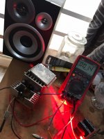
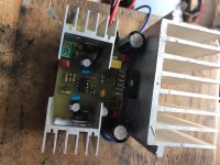
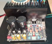
I just completed the Prasi's single sided PCB LM3886.
So i have attached pics for my on/off mV reading getting 22mV on start and ~1.2v on switch off
After a second or so the mV is dropping to 0.9mV
Any recommendations or its safe to sound test my project?
Google Drive: Sign-in
Google Drive: Sign-in
I just completed the Prasi's single sided PCB LM3886.
So i have attached pics for my on/off mV reading getting 22mV on start and ~1.2v on switch off
After a second or so the mV is dropping to 0.9mV
Any recommendations or its safe to sound test my project?
An externally hosted image should be here but it was not working when we last tested it.
Google Drive: Sign-in
Google Drive: Sign-in
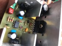
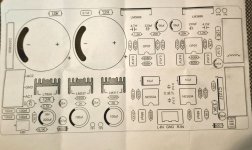
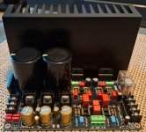
Apex LM3886 Single Side
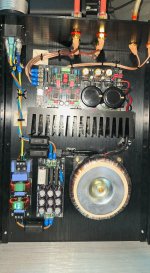
Prasi's single PCB tested with TL072 and works great 🙂
No switch on and off noise, sound is coming out nicely and rich.
After listening to music for about an hour and half, my IC is just still cool, you touch even for +2min.
DC coming at 0.9mV while i listen to music.
Am suing 22-0-22 Toroidal Transformer, test PSU 4700uF/63v x4
Mr.Mile,
added 56R resistors on regs and also managed to loose one jumper. is it perfect now?
reg
Prasi
Prasi's single PCB tested with TL072 and works great 🙂
No switch on and off noise, sound is coming out nicely and rich.
After listening to music for about an hour and half, my IC is just still cool, you touch even for +2min.
DC coming at 0.9mV while i listen to music.
Am suing 22-0-22 Toroidal Transformer, test PSU 4700uF/63v x4
Attachments

Thanks Mr. Mile.
Here are the schematic, stuffing guide, pdf's and gerbers for anyone willing to try🙂.
reg
Prasi
From this post,
https://www.diyaudio.com/forums/chip-amps/162099-lm3886-schematics-pcb-46.html#post5047056
What is the difference between a "Super GainClone" and say the Neurochrome LM3886DR?
I think regulators will shut down randomly. It depends on mfgr.
Some will oscillate and some will latch.
Input voltage too high.
Best regards.
Indeed, things looked suspicious so I googled a couple things. the OPA2134 has an absolute max power input of +/-18V, so if the regulators put out 18.01V (flip a coin and if it's heads they will), the op-amp has its specs exceeded. Likewise, the 7818/7819 regulator inputs are supplied by 35V, just exactly on the edge of their maximum voltage inputs.
I recall a thread a few years ago where several of us were trying to convince someone not to run things at their maximum voltage ratings, and it's not like they were in a major US or European city, they were in an area where parts are harder to get ...
Who "designs" these things?
A "super gainclone" adds an input buffer so that the lm3886 can be run inverting and at lower gain. A DC servo also avoids the use of a feedback capacitor. All these things could slightly improve performances.What is the difference between a "Super GainClone" and say the Neurochrome LM3886DR?
What is the difference between a "Super GainClone" and say the Neurochrome LM3886DR?
You can see measurements of both here: Review: Super GainClone & Super GainClone w/ Klever Klipper by Cordell – Neurochrome
Tom
A "super gainclone" adds an input buffer so that the lm3886 can be run inverting and at lower gain.
The gain difference is minuscule: 10 V/V vs 11 V/V (0.8 dB difference). The main difference is that the inverting configuration of the LM3886 gives a touch lower distortion as the common-mode distortion is eliminated.
The original Super GainClone used fairly high resistor values (10 kΩ) in the inverting stage ahead of the LM3886, which increased the noise quite a bit. You can address that by lowering those resistors to 1 kΩ, but you then need a buffer stage driving the 1 kΩ impedance.
Personally, I would rather use the opamps to perform error correction by making a composite amp as I did in the Modulus-86. That's a different level of design challenge, though.
Tom
This is really nice schematics!
I am new to the diy audio and electronics in general.
What does UF4007 diode does? Connected to the output and +35V? Also, will 56R resistors help during the turn on when voltage from power supply can exceed more than 35V?
Thank you!
I am new to the diy audio and electronics in general.
What does UF4007 diode does? Connected to the output and +35V? Also, will 56R resistors help during the turn on when voltage from power supply can exceed more than 35V?
Thank you!
Attachments
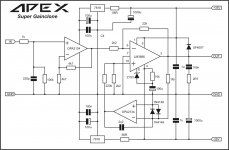
My guess is that the diode is for inductive protection but if so you need one down to minus 35 volts. I don’t think you need it though. Compare the datasheet and the AN-1192
Hello mr, can i use 2X 24V 3A 72W smps suplly foR 2 mono super GC?Apex LM3886 Single Side
Prasi's single PCB tested with TL072 and works great 🙂
No switch on and off noise, sound is coming out nicely and rich.
After listening to music for about an hour and half, my IC is just still cool, you touch even for +2min.
DC coming at 0.9mV while i listen to music.
Am suing 22-0-22 Toroidal Transformer, test PSU 4700uF/63v x4
Hi Tom,Der Verstärkungsunterschied ist minimal: 10 V/V gegenüber 11 V/V (0,8 dB Unterschied). Der Hauptunterschied besteht darin, dass die invertierende Konfiguration des LM3886 eine etwas geringere Verzerrung ergibt, da die Gleichtaktverzerrung eliminiert wird.
Der ursprüngliche Super GainClone verwendet in der invertierenden Stufe vor dem LM3886 relativ hohe Widerstandswerte (10 kΩ), was das Rauschen deutlich erhöht. Man kann das beheben, indem man diese Widerstände auf 1 kΩ senkt. Dazu benötigt man jedoch eine Pufferstufe, die die 1-kΩ-Impedanz steuert.
Persönlich würde ich lieber die Operationsverstärker zur Fehlerkorrektur nutzen, indem ich einen zusammengesetzten Verstärker baue, wie ich es beim Modulus-86 getan habe. Das ist allerdings eine ganz andere Design-Herausforderung.
Tom
I built an LM3886 amplifier, and it sounds fantastic. I swapped the NE5534 for an OPA1655 and the OP07 for an OPA277. I also replaced the 10uF electrolytic capacitor on the op-amp with a 10uF Wima MKS. Can you explain what I built? It sounds better than my Nait 5si.
Attachments
noHello mr, can i use 2X 24V 3A 72W smps suplly foR 2 mono super GC?
- Home
- Amplifiers
- Chip Amps
- LM3886 Schematics + PCB