Yes; that's why I wrote "to show approx. measurement limits above ~200Hz".The air core should not have current distortion unless it can vibrate mechanically or there is some iron nearby. Do you think this was the case or are we seeing the limitations of the amplifier?
I did not investigate the cause. Like I said, those were done using the headphone output of an audio interface through a 100Ω resistor. It's probably a combination of the headphone amp distorting a bit along with perhaps some thermal modulation of the sense resistor (1/4W metal film).why would it increase below 100 Hz?
The main point of that test was to show the odd-order harmonics in the current through the midrange and treble as these are mostly caused by the nonlinear behavior of the steel in the magnetic circuit.

Let's continue, shall we?
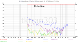
LEFT: B&W 6" FST midrange from 801D4 (2021)
RIGHT: B&W 6" FST midrange from B&W Sound System (2014)
Spheroidal enclosure in background, with Eagle branded non-inductive resistor, 27 ohm, 10W series resistor.

Here's the front view- showing both mounted in spheroidal enclosure:

Our software REW applies a 1/24th octave smoothing filter to the fundamental in the Distortion screen.
This is fixed and cannot be turned off (as of current REW 5.4 Beta 80)
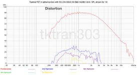
Let's start with the 801D4 6" FST (Left), and we apply an exponential sine sweep at 2V.

That's a "low distortion" driver, except for what's happening below 400Hz. You would be forgiven for that, after all, this is a midrange, and design for use above 400Hz
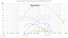
Let's connect the resistor (as pictured above) in series with the positive terminal of the speaker. For convenience, this is done externally, but of course there's no difference if it's done internally, after the (non-magnetic) binding posts. Here I show it in black and white, to help delineate differences:

Looks like we do lose a lot of voltage sensitivity (17dB!) And there seems to be a peak around 250Hz.
Here's the impedance sweep of the driver, in free air:

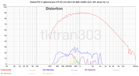
But we need to compare apples with apples. Now now we apply some EQ to correct the frequency response changes caused by the 27 ohm series resistor.

Ahah! As we say in Australia, now we're cooking with gas!
Let's add some EQ, like you would do in a speaker:

Can we view this another way, that some of friends prefer:

How does that compare to a 96dB "standard" that some of our friends, eg. @bikinpunk likes to measure at.
Here's a 6" FST, as used in the 800 series 4 centre channel: appropriately named HTM81:

Disclaimer-
This study was carried out entirely independently, with no financial backing—direct or indirect—from external sources. All findings, interpretations, and conclusions are solely those of the researcher, free from external influence or bias.
Thanks to the usual friends at diyAudio for proof-reading and corrections prior to publication, but I take responsibility of all mistakes made in charts/graphs within the 30 min publishing time limit.
NEXT UP: KEF Reference/Blade META UniQ midrange (2022) 😉
LEFT: B&W 6" FST midrange from 801D4 (2021)
RIGHT: B&W 6" FST midrange from B&W Sound System (2014)
Spheroidal enclosure in background, with Eagle branded non-inductive resistor, 27 ohm, 10W series resistor.
Here's the front view- showing both mounted in spheroidal enclosure:
Our software REW applies a 1/24th octave smoothing filter to the fundamental in the Distortion screen.
This is fixed and cannot be turned off (as of current REW 5.4 Beta 80)
Let's start with the 801D4 6" FST (Left), and we apply an exponential sine sweep at 2V.
That's a "low distortion" driver, except for what's happening below 400Hz. You would be forgiven for that, after all, this is a midrange, and design for use above 400Hz
Let's connect the resistor (as pictured above) in series with the positive terminal of the speaker. For convenience, this is done externally, but of course there's no difference if it's done internally, after the (non-magnetic) binding posts. Here I show it in black and white, to help delineate differences:
Looks like we do lose a lot of voltage sensitivity (17dB!) And there seems to be a peak around 250Hz.
Here's the impedance sweep of the driver, in free air:
But we need to compare apples with apples. Now now we apply some EQ to correct the frequency response changes caused by the 27 ohm series resistor.
Ahah! As we say in Australia, now we're cooking with gas!
Let's add some EQ, like you would do in a speaker:
Can we view this another way, that some of friends prefer:
How does that compare to a 96dB "standard" that some of our friends, eg. @bikinpunk likes to measure at.
Here's a 6" FST, as used in the 800 series 4 centre channel: appropriately named HTM81:
Courtesy: ErinsAudioCorner.com
Reference: https://www.erinsaudiocorner.com/loudspeakers/bower_wilkins_htm81_d4/
Reference: https://www.erinsaudiocorner.com/loudspeakers/bower_wilkins_htm81_d4/
What do you think? Does "current drive" have any merit/promise?
Disclaimer-
This study was carried out entirely independently, with no financial backing—direct or indirect—from external sources. All findings, interpretations, and conclusions are solely those of the researcher, free from external influence or bias.
Thanks to the usual friends at diyAudio for proof-reading and corrections prior to publication, but I take responsibility of all mistakes made in charts/graphs within the 30 min publishing time limit.
Appendix:
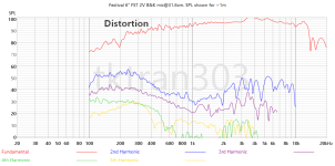
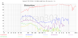
Similar process and measurements with the FST from the 2014 B&W Sound System without commentary
Similar process and measurements with the FST from the 2014 B&W Sound System without commentary
NEXT UP: KEF Reference/Blade META UniQ midrange (2022) 😉
Attachments
Last edited:
Thanks for the measurements.What do you think? Does "current drive" have any merit/promise?
Of course it has merit for midranges (only!) in active loudspeaker systems (with high impedance output midrange amps). But it is not usable for woofers in the low frequency department.
It may seem so.
When you say "low frequency department" - what frequency and SPL are you considering?
For low bass, we might have to use another method, like double reverse inverted which reduces deep bass H2, likely due to asymmetry in suspensions bigger cabinets, ported cabinets etc if we want to reduce distortion or increase SPL.
I like to use the the (known) tools at my disposal, and am not married to, whether it be theory or practice, active or passive, or voltage or current drive, DSP or ASP, IIR or FIR, MDF or plywood, aluminum or 'plastics', screws or adhesives, sine sweeps or FSAF...
Coming soon, a story about spiders...
Below 150 Hz for small woofers, below 100 Hz for larger. Any SPL.When you say "low frequency department" - what frequency and SPL are you considering?
Interesting assertion.
Here is a 10" woofer.
Free air impedance trace are below:

Is this a small woofer? It's a 10", as used in this speaker: (801D4, parallel in pairs, ported)
But just one, and placed into a 1cu ft sealed test cabinet with, say, medium fiberglass fill. *
The mic is in the near field, with the wide open (1000ms). Absolute SPL shown (no correction for distance applied)
Here's a few levels, first voltage driven, then with a couple of 20 ohm 10W resistors in parallel = 10 ohm, 20W continuous power handling.
Attempts to EQ the "current drive" amplitude response as closely to the the voltage driven counterparts.
It’s about +/- 1dB for most of it, which I think is useful enough. We’re really interested in only below 150Hz, as you say, but I though I would include higher, so we can see the increasing imprecision of nearfield measurements (fuzziness increases as increases)

Voltage driven at 0.8V ~75dB @100Hz @1m (2pi)

Insert the 10R resistor, EQ for same response, then feed it 1.42V to match the fundamental:

Now 2.83V: 86dB @100Hz @1m (2pi)

EQ and "current driven"

5.65V voltage driven: 92dB @100Hz @1m (2pi)

Current driven:

VituixCAD2 simulation with 6-pack showing simulation at 0.8V, 2.83V and 5.65V in voltage drive mode.

@Sonce
Shall we refine our hypothesis?
Here is a 10" woofer.
Free air impedance trace are below:
Is this a small woofer? It's a 10", as used in this speaker: (801D4, parallel in pairs, ported)
But just one, and placed into a 1cu ft sealed test cabinet with, say, medium fiberglass fill. *
The mic is in the near field, with the wide open (1000ms). Absolute SPL shown (no correction for distance applied)
Here's a few levels, first voltage driven, then with a couple of 20 ohm 10W resistors in parallel = 10 ohm, 20W continuous power handling.
Attempts to EQ the "current drive" amplitude response as closely to the the voltage driven counterparts.
It’s about +/- 1dB for most of it, which I think is useful enough. We’re really interested in only below 150Hz, as you say, but I though I would include higher, so we can see the increasing imprecision of nearfield measurements (fuzziness increases as increases)
Voltage driven at 0.8V ~75dB @100Hz @1m (2pi)
Insert the 10R resistor, EQ for same response, then feed it 1.42V to match the fundamental:
Now 2.83V: 86dB @100Hz @1m (2pi)
EQ and "current driven"
5.65V voltage driven: 92dB @100Hz @1m (2pi)
Current driven:
VituixCAD2 simulation with 6-pack showing simulation at 0.8V, 2.83V and 5.65V in voltage drive mode.
*Sure I could have put in more (see impedance trace showing internal reflection around 90Hz)
@Sonce
Shall we refine our hypothesis?
Attachments
Last edited:
Conclusion: The use of a series resistor (or a simulted one) would still allow some damping around fs while showing significant distortion reduction. This could be interesting for the use of low-Q drivers in closed boxes.
Regards
Charles
Regards
Charles
.. and also level was matched? I.e. same SPL for both measurements? Amp need to swing 20 dB more voltage all of a sudden...But we need to compare apples with apples. Now now we apply some EQ to correct the frequency response changes caused by the 27 ohm series resistor.
It looks like you did but wasn't mention in text... 😉
//
Hi, you can play around with this in VituixCAD enclosure tool, there is the Rs field in the filter tab.Conclusion: The use of a series resistor (or a simulted one) would still allow some damping around fs while showing significant distortion reduction. This could be interesting for the use of low-Q drivers in closed boxes.
Regards
Charles
Electrical damping is lost quite fast as yoibstart increase Rs, so if you need electrical damping use series inductor instead.
You could also replace electrical damping with mechanical, which you can experiment with VituixCAD enclosure tool as well. If you add the Rs, try how much you need to increase enclosure size, add damping material, and possibly make the box leak, to restore similar Q. Design your box with the particulsr series impedance, doesn't have to be zero as it is by default on all simulators.
.. and also level was matched? I.e. same SPL for both measurements? Amp need to swing 20 dB more voltage all of a sudden...
It looks like you did but wasn't mention in text... 😉
//
Does your browser not allow you to click to view full images?
I can lead a man to water, but you must click and compare yourself!


Thinking about all of the above, I was wondering if similar results would be achieved if, instead of the usual Rdc of 3,x or 6,x Ohms for the voicecoil, a 20 Ohms Rdc voicecoil would be used in the driver motor. As an addditional bonus BL would increase. Of course sensitivity would drop.
Sorry if I was not clear enough. I was referring to the lack of electrical damping, not to the distortion reducing ability of the current drive. Steady state measurements can not reveal impulse behavior (i.e. music) of current driven woofer around impedance peak. If you measure impulse behavior of that closed-box loudspeaker with "burst" signal (several periods of sinusoidal signal on, then off), you will see that with current drive signal will settle in time longer than with voltage drive. Audibly, current drive will sound boomy, not tight as it should be.Interesting assertion.
Here is a 10" woofer. ...
10" woofer is a big driver in the hi-fi world.
Last edited:
I made that experiment. Sound was so boomy in the bass, it was not bearable.Thinking about all of the above, I was wondering if similar results would be achieved if, instead of the usual Rdc of 3,x or 6,x Ohms for the voicecoil, a 20 Ohms Rdc voicecoil would be used in the driver motor.
Yeah it's something you could do, although many parameters would change I believe, weight and power handling and so on, but I'm no motor designer so don't comprehend what would be affected. You could also do motor without iron. It's game in optimization for your application, like always.Thinking about all of the above, I was wondering if similar results would be achieved if, instead of the usual Rdc of 3,x or 6,x Ohms for the voicecoil, a 20 Ohms Rdc voicecoil would be used in the driver motor. As an addditional bonus BL would increase. Of course sensitivity would drop.
You could replace missing electrical damping by using suitable enclosure alignment by adjusting size, filling and leakage.Sorry if I was not clear enough. I was referring to the lack of electrical damping, not to the distortion reducing ability of the current drive. Steady state measurements can not reveal impulse behavior (i.e. music) of current driven woofer around impedance peak. If you measure impulse behavior of that closed-box loudspeaker with "burst" signal (several periods of sinusoidal signal on, then off), you will see that with current drive signal will settle in time longer than with voltage drive. Audibly, current drive will sound boomy, not tight as it should be.
10" woofer is a big driver in the hi-fi world.
How about same number of turns but thin wire to increase Rdc without affecting Le. Not sure what else would change, mass and power handling at least.@Boden No. Increasing BL by more windings will increase Le accordingly, and so the nonlinear contribution. The fractions of Rdc vs. Le stay same, and so the current distortion.
Impossible.You could replace missing electrical damping by using suitable enclosure alignment by adjusting size, filling and leakage.
Lack of damping in current drive can not be overcome by any possible manipulation of size, filling and leakage.
Then why is everyone always trying sell me voltage drive up to 20kHz?Below 150 Hz for small woofers, below 100 Hz for larger. Any SPL.
Because it is the cheapest way to get good sound from passive loudspeaker and a single amplifier, for frequencies from 20 Hz up to 20 kHz. Current drive will reduce distortion above 100-150 Hz (not necessarily for the tweetr) , but you need active loudspeaker system with at least two amplifiers - one for the woofer, one for mid/high driver. Or, some expertly designed amplifier with variable output impedance vs frequency.Then why is everyone always trying sell me voltage drive up to 20kHz?
Last edited:
- Home
- Loudspeakers
- Multi-Way
- Experiments with the current drive