^ I think it's fantastic that you posted your experience, and FWIW I never took any of your posts as product bashing. I think a ton of people (including myself) learned a great deal. Examining what occurs under various failure modes and even under standard operating conditions for something so seemingly simple as a fuse and a drawer was/is fascinating. I'll bet there are a lot of folks like me that won't take it for granted in the future after reading through the thread.
Your experience spurred me to look into my fuses / drawers / PEMs / combinations and read the standards for their rating characteristics. I (incorrectly) assumed that the current / voltage ratings were the bulk of what mattered. Turns out... nope.
Cheers!
Your experience spurred me to look into my fuses / drawers / PEMs / combinations and read the standards for their rating characteristics. I (incorrectly) assumed that the current / voltage ratings were the bulk of what mattered. Turns out... nope.
Cheers!

4304.4045 is the part number for the new model in the kit, 4304.6090 is the version that used to be included. According to the datasheet the tabs on the fuse holder are meant to be soldered, while the ones on the switch are quick-connect.For awareness, the tabs for the 2 fuse on the Schurter 4304.4045 PEM supplied in the diyaudiostore back panel kit provided for years are 2.8mm. The other 5 tabs (4 on the switch, and 1 on the ground) are 5mm.
https://www.schurter.com/en/datasheet/typ_6765.pdf
https://www.schurter.com/en/knowledge/terminals
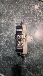
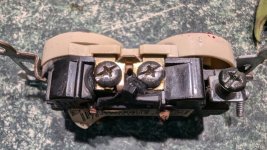
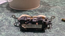
This thread caught my eye because last year the power went out in part of our house and after tracing it back found that the first two outlets on the circuit worked, but the next one didn't along with everything that came after it. After pulling it we saw it had melted and that's where the disconnect happened. This outlet used the push-in connections instead of the screw terminals. As the years went on this connection degraded and it eventually melted. This seems to be a common issue with this style connection.
There could be a number of reasons for the fuse connection being poor, but it looks similar to what happened with my outlet.
Attachments
Well then, I guess that solder theory is likely not the issue.According to the datasheet the tabs on the fuse holder are meant to be soldered,
Thanks for catching the error!4304.4045 is the part number for the new model in the kit, 4304.6090 is the version that used to be included.
Bullseye. I can't believe I really never considered this being a problem....just got everything recommended amperage. Fuse is a fuse is a fuse and so forth.^ I think it's fantastic that you posted your experience, and FWIW I never took any of your posts as product bashing. I think a ton of people (including myself) learned a great deal. Examining what occurs under various failure modes and even under standard operating conditions for something so seemingly simple as a fuse and a drawer was/is fascinating. I'll bet there are a lot of folks like me that won't take it for granted in the future after reading through the thread.
Your experience spurred me to look into my fuses / drawers / PEMs / combinations and read the standards for their rating characteristics. I (incorrectly) assumed that the current / voltage ratings were the bulk of what mattered. Turns out... nope.
Cheers!
Noticed another item, print on side of new PEM from DIYstore rear panel kit also shows 10 amp @ 40 C. I'm pretty sure I was over 40C! This new PEM only has 3 tabs so less soldering, crimping or what ever connection method you use.
It also contains some sort of filter, giving a slightly larger unit that is a touch too large for old size cutout.
Russellc
Well. The posts in question were the ones associated with the fuse drawer. Interesting. Parts should be here tomorrow.
Will be keeping a close eye on amps with much fuse drawer feeling.
Will be keeping a close eye on amps with much fuse drawer feeling.
Uh oh....not sure which I ordered... Check email. Oh well, I will use them eventuallyWell then, I guess that solder theory is likely not the issue.
Thanks for catching the error!
Checked invoice, I actually ordered the correct one. On a worse note, another delay from digikey, still darn quick, but now Tuesday.
Last edited:
All parts have arrived, including 2.5 amp slowblow little fuse, 16 and 20 amp panel mount fuse holders and 3 new PEM units that came with the back panel parts kits, not the new one.
Time this weekend, will keep all informed!
I hate to stir the pot, but seems like their are many opinions of how these "3 in 1" units should be wired. Some warn of using the faston, especially in some climates as corrosion can begin to form hurting connectivity, resulting in problems down the line. The second warning seems to be not at that end of the faston, by how it is connected to the wire itself. Warns are usually in regard to being improperly crimped. Avoidance being easy, strip off plastic and solder.
A previous post indicated that schurter indeed recommends soldering the wire to post on two that go from fuse drawer, and fastons (soldered to wire) on other connections. This is method that seems most sound to me at this time. Checking for any damage along the way.
BTW, new version on back panel kit only has two connectors, and a ground connector. Inclined to solder ground, faston on line and neutral?
Maybe proper and safe installation can be enjoyed by all!
Thanks for reading.
Russellc
one of the tricks I learned, while soldering fancy (no need to name that Drek) IEC back panel thingies given by customers, to prevent displacement of pins while soldering, just plug IEC plug in, and it'll keep them in place while soldering
after minute or two, when metal is cold, unplug and everything is neato
again, my practice (ZM Omnichicken) is - IEC with integrated fuse or even switch too - good "just" for preamps and things as such
after minute or two, when metal is cold, unplug and everything is neato
again, my practice (ZM Omnichicken) is - IEC with integrated fuse or even switch too - good "just" for preamps and things as such
I always start with the data sheet. Schurter does make units that have terminals intended for soldering. If you want to solder... maybe get one of those.BTW, new version on back panel kit only has two connectors, and a ground connector. Inclined to solder ground, faston on line and neutral?
You'll get just as many opinions as people you ask; mine is just one of them, and it's likely not to be the best one.
If you're using fastons, how about just crimping them properly with matching wire and crimping tool? Iwiss...Warns are usually in regard to being improperly crimped. Avoidance being easy, strip off plastic and solder.
Oh, I have the equipment to do that. Everyone here will tell you it leads to a service problem down the road.
I have a rather pricey crimper, so I strip off the plastic, crimp, then solder. It's the other connection, the slide on part my question pertains to. The new PEMS I received are what use to be in the panel kits, when I get home I will check and post which unit it is. Then data sheet will say what it is, solder type or no, will Iinstall accordingly
I have a rather pricey crimper, so I strip off the plastic, crimp, then solder. It's the other connection, the slide on part my question pertains to. The new PEMS I received are what use to be in the panel kits, when I get home I will check and post which unit it is. Then data sheet will say what it is, solder type or no, will Iinstall accordingly
If you ordered the unit that used to come with the kits, I posted the link to the data sheet earlier in the thread. 🙂
The PEMs provided with the previous back panel parts kits are Schurter 4304.6090
https://www.mouser.com/datasheet/2/358/typ_6765-1275662.pdf
Thanks I think it was an earlier post of yours that showed the number, and that is what I ordered. I'm not at home now to check. Thanks again.
I thought this would be a constructive post, but it isn't turning out that way. Plenty of knowledgeable people here to ask via DM, so let's just shut this one down.
Russellc
I thought this would be a constructive post, but it isn't turning out that way. Plenty of knowledgeable people here to ask via DM, so let's just shut this one down.
Russellc
Russelic
You are correct that Fastons can have an issue, not with the crimp (assuming a proper tool) but with the slide connection. They have a relatively small cycle life before needing to be "tightened". If they slide on easily they probably need to be re-toleranced, which is not an exact science for a user.
You are correct that Fastons can have an issue, not with the crimp (assuming a proper tool) but with the slide connection. They have a relatively small cycle life before needing to be "tightened". If they slide on easily they probably need to be re-toleranced, which is not an exact science for a user.
Soldering won't make faston stuff designed to be crimped any better. On the contrary and even more so with lead free solder. Maybe it was the cause of the defect after all (current is unknown). Just saying.
Last edited:
I will also order the version that another member mentioned a few posts up, that was recommended to be soldered. Seems to reason it would be able to handle more heat. Not like it won't get used!
Maybe don't listen to opinions and just follow data sheet recommendations by the manufacturer. Stuff is designed for a goal and will only function reliably over a longer period when installing it as intended/according official requirements. Also always measure currents so you actually know what current runs and what value the fuse needs to be and to know/calculate its power loss to the environment. It would not hurt to inspect cases where fuse holders heat up with an IR thermometer and also measure current in those devices.
I am aware it is questionable advice today but if wiring needs to be soldered to IEC inlets I recommend to use 60/40 solder and not lead free stuff (specifically for this purpose). That will reduce the solder time and it will result in mechanically stronger and more reliable solder joints. The tips by Zen Mod in post #129 will also help.
There is not much wrong with faston when using good quality stuff even in harsh conditions. In pro/high power/DC electronics these are used extensively. Trouble is that quality differences exist. Official faston by the known brands have a retention mechanism that works pretty well, sometimes even giving trouble to remove connectors. Now look at the average connector you see in the field. In cheap electronics they sometimes don't have enough contact pressure or they can be taken off with a finger.
Last edited:
- Home
- Amplifiers
- Pass Labs
- Shurter on/off fuse units