Yes C7 need to be of good quality. Look in the start of this thread. They are discussed there.
Kind Regards
Kind Regards
This is good info. Have had those problems. Do you mean i parralel or series?Stef ,
In the past I did get a tip from Hugh Dean ( Aspen Amps ) regarding the use of FQA/PF and IXTQ power FETs .
Solder a 470p and 47R resistor between drain and gate to avoid future problems which could happen due the high transduction of those FETs .
This way you slow them down a bit and protect too for the use in amps .
Hello,
I have already tried this. It causes an oscillation (= high consumption on the power supply).
It works well without so why add things.
Stef.
I have already tried this. It causes an oscillation (= high consumption on the power supply).
It works well without so why add things.
Stef.


Hello,
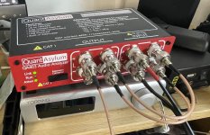
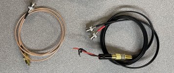
The configuration is very simple.
The 2 x BNC-RCA differential cable can be bought directly on eBay. For stereo testing, you need 2 BNC-RCA cables, 2 2xBNC-RCA cables and 2 loads.
Regards,
Stef.
The configuration is very simple.
- One BNC-RCA 1m cable for the output.
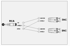
- One 2xBNC-RCA differential 1m cable for the input (to avoid ground loop).
- Two BNC-BNC 15cm cables for the interconnection of the second channel.
- A 100W 8 Ohm load.
The 2 x BNC-RCA differential cable can be bought directly on eBay. For stereo testing, you need 2 BNC-RCA cables, 2 2xBNC-RCA cables and 2 loads.
Regards,
Stef.
Attachments
Last edited:
Thank You
Have now ordered the cables you recommend.
Really love the mini. Use it as my main amplifier.
Have now ordered the cables you recommend.
Really love the mini. Use it as my main amplifier.
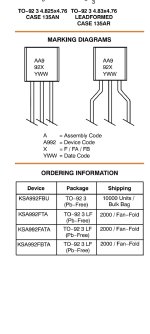
I know , bud is there a reason for taking the FBTA . Only different I see is the highest hfe of the FBTA . Is it for this Stef is taking that one ?
Hello everyone! I am planning to embark on building a pair of Turbo units.
Do you have any suggestions on what parts should be checked for tight tolerance or matched?
Many thanks!
Do you have any suggestions on what parts should be checked for tight tolerance or matched?
Many thanks!
Stef ,don't you mean D3 instead of D4 ?Hi!
A pair of Vishay 100V mosfet.
Q1': SI2328DS
Q4': SI2325DS
With the SMD parts and 60V rails, zeners D2 and D4 MUST BE REPLACED by 16V 1N5246B zener to get 14V.
With the SMD parts, we get -3dB more on the 50Hz rejection.
I replaced Q6 with FQPF3N80C. With the Toshiba I got burst of oscillation > 32V. With the FQPF3N80C it's ok until the clip à 35V.
Stef.
Oops, you're right.
I 've updated the doc.
https://github.com/stefaweb/Q17-Amplifier/blob/main/Q17-Mini-3.0/Q17-Mini-SMD-BOM.md
Regards,
Stef.
I 've updated the doc.
https://github.com/stefaweb/Q17-Amplifier/blob/main/Q17-Mini-3.0/Q17-Mini-SMD-BOM.md
Regards,
Stef.
45Vac is too high.
45Vac is 45 x 1.44 = 63Vdc peak
I'd say 43/44Vac is the maximum. There's little point in powering it too high. It won't add any power and will degrade the SNR.
@radu19880625: The output mosfets should be sorted as well as the BS250s (unless you use an NDC7003P instead).
Regards,
Stef.
45Vac is 45 x 1.44 = 63Vdc peak
I'd say 43/44Vac is the maximum. There's little point in powering it too high. It won't add any power and will degrade the SNR.
@radu19880625: The output mosfets should be sorted as well as the BS250s (unless you use an NDC7003P instead).
Regards,
Stef.
- Home
- Amplifiers
- Solid State
- Q17 - an audiophile approach to perfect sound