Yes, they do, really 😍
I have to order leaded solder, have only lead-free, which is for sissies, I know...
I have to order leaded solder, have only lead-free, which is for sissies, I know...
The good news is you don't really need the SMD caps on the opamp, you can always attach small film caps to the leads of the electrolytic on the bottom of the PCB if you desire film bypass.
If you have already the PCB stuffed with components, getting the SMD Jfet attached will be quite difficult, you may just have to order the K170s.
If you have already the PCB stuffed with components, getting the SMD Jfet attached will be quite difficult, you may just have to order the K170s.

Lead-free solder and SMDs is not really a problem ... so far, I used two different methods:
First method:
Worked perfectly for Wayne's BA 2018, for example. I didn't use flux.
This is the solder I used:
Silver Solder for SMD
For my regular work, I use that solder in the 1mm variant:
Silver Solder
The same solder has also been sold in Europe under the Fixpoint brand (same part number). I use this solder for 15 years now, everything is still holding up well.
Second method that I use now; for example I used it on the Pearl 3:
You only need very little solder paste on the pads - best practice with one of the SMD practice kits before committing to a real board.
This paste works perfectly for me:
SMD Solder Paste lead-free w/ silver
Using this method, I can work with SMD parts very relaxed. Also, I don't need magnifying glasses for this.
I really liked working on the Pearl 3 this way, had an almost meditative or Zen-like quality to it ... 🙂
Regards, Claas
First method:
- use the sharpest pencil tip for the soldering iron you can get, set to 350 degrees C
- use very thin solder, 0.35mm works well
- I put on magnifying glasses
- put a tiny bit of solder on one of the pads
- place & press the part down on the pads with a toothpick
- a quick and light touch of the pencil tip to the pad that has the solder will tack down the part
- solder the other pads with the pencil tip and fed with a bit of solder from the spool
- solder the first pad properly
Worked perfectly for Wayne's BA 2018, for example. I didn't use flux.
This is the solder I used:
Silver Solder for SMD
For my regular work, I use that solder in the 1mm variant:
Silver Solder
The same solder has also been sold in Europe under the Fixpoint brand (same part number). I use this solder for 15 years now, everything is still holding up well.
Second method that I use now; for example I used it on the Pearl 3:
- get a hot-air station, can be an inexpensive one. Set to 400 degrees C for working with lead-free solder
- clean the pads with Isopropanol
- use a syringe with a very narrow tip (cannula ? = blunt needle)
- put a tiny bit of solder paste onto the pads (no additional flux needed)
- place the parts
- heat with the hot-air gun until the paste first melts and then becomes silvery. Not longer !
You only need very little solder paste on the pads - best practice with one of the SMD practice kits before committing to a real board.
This paste works perfectly for me:
SMD Solder Paste lead-free w/ silver
Using this method, I can work with SMD parts very relaxed. Also, I don't need magnifying glasses for this.
I really liked working on the Pearl 3 this way, had an almost meditative or Zen-like quality to it ... 🙂
Regards, Claas
Last edited:
Yes, I already thought I will remove the mess and use normal caps 👍
Leaded solder... Sales to private individuals are prohibited in the EU... (if you don't have any other problems...). I had to register with a supplier using my own company details so I could order leaded solder (supposedly specifically for SMDs).
Leaded solder... Sales to private individuals are prohibited in the EU... (if you don't have any other problems...). I had to register with a supplier using my own company details so I could order leaded solder (supposedly specifically for SMDs).
I found an eBay seller from Poland that did sell leaded solder to me without checking for company credentials ... I bought my last spools November 2023, but apparently the offer is still on.
Sometimes, I do need leaded solder - for example, when restoring 70's and 80's equipment, or when I want to solder AWG13 to a big ground plane ...
Regards, Claas
Sometimes, I do need leaded solder - for example, when restoring 70's and 80's equipment, or when I want to solder AWG13 to a big ground plane ...
Regards, Claas
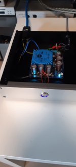
Todays progress... only the JFets are missing.
Otherwise I could already listen to music with it 👍

Otherwise I could already listen to music with it 👍
Yes... so I ordered 2 quads from the shop now 👍The good news is you don't really need the SMD caps on the opamp, you can always attach small film caps to the leads of the electrolytic on the bottom of the PCB if you desire film bypass.
If you have already the PCB stuffed with components, getting the SMD Jfet attached will be quite difficult, you may just have to order the K170s.
Hi,
boards finished.
The solution for the smd-thingies was the leaded solder, the DRV135 went on without issues.
And I sm'd the 1uF caps (upper left corner)... okay, not the classical way, but they ARE surface mounted 😀
The other two are mounted on the solder side of the boards.
I use the LSK170 from the shop (they arrived in 2.5 days after placing the order, just great), and therefore I changed the resistors as recommended to 22 ohms. Further, I changed R27 to 680 ohms, this should be fine according to the thread here, but I of course will make a measurement too.
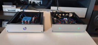
Meanwhile I have also finished my pearl 3 kit.
Very happy with the result, after just few hours burning in so far.
The only thing I need to change... I don't like the green LEDs plus
the are far too bright...


Very happy with the result, after just few hours burning in so far.
The only thing I need to change... I don't like the green LEDs plus
the are far too bright...
Attachments

You'll probably want to adjust the series resistor no matter what the LED color.
Most people set them very bright for some reason.
Most people set them very bright for some reason.
Yes, already checked the schematic to identify the right resistor.
The LED of the power switch is blue hence I will also go for blue LEDs on the Amp side.
The LED of the power switch is blue hence I will also go for blue LEDs on the Amp side.
LED’s have gotten very efficient as of late. The resistors on our integrated amp displays went up in value over one hundred times when the discontinued seven segment was changed to the new version. I wonder if LED lighting has driven this.
Hi,
today I will fire up (okay, turn on...) my Pearl for the first time. I wonder if my fuse calculation is correct.
A 15VA donut at 230V results in a 65mA fuse – is that correct? It seems a bit too low to me.
What is recommended? Many thanks!
today I will fire up (okay, turn on...) my Pearl for the first time. I wonder if my fuse calculation is correct.
A 15VA donut at 230V results in a 65mA fuse – is that correct? It seems a bit too low to me.
What is recommended? Many thanks!
I totally agree regarding brightness.
If the indicators keep catching your attention, they are just too bright. I was "unlucky" to get a bunch of extremely
efficient LED´s. 270K res = too bright.
Ended up with 910K, but then they were uneven in brightness. So...... 470K + an old fasioned 1Mohm/½watt trimpot in series (each channel)
to reach the preferred brightness (and both at the same level. To defocus the beam, I filled the holes in the frontplate with
UV-glue and hardned it with an UV-flashlight.
Now:

As for the fuse........ I had both 200 and 315mA-T blow on startup, possibly due to charge using a very large capacitor bank, and
ended up with a mains fuse of 400mA/slo blo. Never blew one again.
If the indicators keep catching your attention, they are just too bright. I was "unlucky" to get a bunch of extremely
efficient LED´s. 270K res = too bright.
Ended up with 910K, but then they were uneven in brightness. So...... 470K + an old fasioned 1Mohm/½watt trimpot in series (each channel)
to reach the preferred brightness (and both at the same level. To defocus the beam, I filled the holes in the frontplate with
UV-glue and hardned it with an UV-flashlight.
Now:
As for the fuse........ I had both 200 and 315mA-T blow on startup, possibly due to charge using a very large capacitor bank, and
ended up with a mains fuse of 400mA/slo blo. Never blew one again.
So, Pearl 3 on the test bench, everything is fine, no smoke of course, LEDs are on - and now I have to decide: should I go to bed or should I make the maiden listening? 🤔 

it would be interesting to see (hear) how quiet the unhoused circuit can be.
Especially if you have dimmer lights in your listening room ceiling.
- Home
- Amplifiers
- Pass Labs
- Pearl 3 Burning Amp 2023