Still need tocdigest the paper, but i will search a picture showing the dbl change to compensate time change when moving to different list pos.
I just was lucky, i found it and scanned the 3 sheets in a PDF format. It is in Dutch, but a quick intro into this matter:
Page 100 Fig. 41 shows the spread of a monophonic signal over the frequency range. Basically showing the hearing lateral directivity , and on top the impact of phase-shifts introduced by xo filter. You can assume first order or second order.
Page 100-102 in Dutch gives more detail.
Page 103 is about crosstalk i neglected this.
Page 114 Fig. 49 shows the required channel separation needed to prevent audible reduction of stereophonic quality.
On page 114 starts chapter 8.3 and covers the " correct stereo sit" we nowadays refer to as listening position.
Page 115 Fig.50 shows the testcase with 9 listening positions.
Page 116 Fig.51 shows the trading of intensity and time differneces
Rechterkant luider = Rightside louder
Linkerkant eerder = Leftside earler
Page 117: Fig.52 a polar plot of the intensity - time trading values required for the 9 LP's to keel the stereophonic image intact.
Systems have been built to meet these findings and they were amazing in the sterophonic image aka soundstage aka whatever word is used to describe the reproduction of the soundstage as recorded in the recording.
Short anekdote, these pages arre from a document of more than 50 years ago. The scans are from mid 70's. Early 80's i bumped into a former sales director of Philips, and when discussing these findings he remembers the guys who did this research and a lot more. They were highly educated researchers from Philips NatLab who in WW2 had to hide from the Germans, somewhere in the woods around Eindhoven.
They had 'ample time' to do research and focused on stereophony. So the findings are pretty old but still hold. They did a lot more, but that is about records and record players. Basically the Goldmund recordplayers of the late 70's early 80's had incorporated all these guys researched and found out (not to say that Goldmund used that research). One example, a rubber matt on the turntable is the poorest solution.
Now coming back to your question about moving to different positions to listen.
You can take this research and turn it around.
In essence the direction sensitivity curve of our hearing and the spl-time trading can tell you how much the polar response of a speaker impacts the imaging of the reproduced sound for a given listening position.
Addition: at high frequencies strong beaming can cause your hearing to locate the driver, and thus rather detrimental for the stereo imaging.
Happy digesting ;-)
Attachments
Last edited:

Yes !^ he forgets to explicitly mention here that this is from the home listening perspective, where early reflections dominate perception and ruin the "clarity", and make the artificial wide imaging. That's nice sound for many, but really the great sound in my opinion isn't this one
Yes !Most important difference is whether your brain pays attention to the sound or not, auditory system ability to lock in, and when it does the detail is there and image could be as big as you want, depending how you have positioned the system. For some reason this aspect is always somehow present on papers but as a side note, like on this one.
Yes ! again...The "near field" sound is very involving, the HiFi sound to me, and it goes deep within and is very emotional in a way. On the other hand the sound thats available farther away is relaxing, I can do work and concentrate or fall as sleep, because my brain is not having the attention to it.
I think we can all agree that shape of the frequency response (FR), both on and off axis, determines at least 90% of loudspeaker sound quality. Any speaker which gets the FR right is going to sound good, even if it has other flaws. We can tolerate an elevated level of HD and IMD, some compression, some resonances, or some baffle edge diffraction, as long as the on-axis FR is flat and smooth, and the ER and power response is appropriately shaped. The corollary is that it is a waste of time and resources to concentrate on those other aspects if the basic FR is flawed. A speaker with a badly flawed FR will not be made better by lowering the distortion, improving the power compression, giving it a CSD cabinet, or minimizing edge diffraction. It will still be badly flawed.
But... Once we have achieved an excellent FR performance, all sorts of other characteristics and performance metrics start to become important. Improving from 90% to 99% is very challenging, because all these other aspects need to be improved and optimized without degrading the fundamental FR performance. I firmly believe that managing and reducing high frequency diffraction (the diffraction above the baffle step) is an important part of the process when going from 90% to 99%.
j.
One thing that often seems missing in discussions like this is the effect that the cabinet shape and diffraction signature has on the difference between on axis and off axis sound. The Ascend Sierra shown in the document linked (I can't bring myself to call it a paper) is a good example and the designer has done a good job of managing the compromise. Because of the size, shape and lack of edge treatment there is an off axis gain that can be seen in the normalized polar diagrams. If the on axis or listening window is made flat there will be an off axis peak. This is almost always quite audible in a negative way. Here the designer has dipped the on axis and listening window to keep the off axis really smooth. A good choice but it is a compromise forced by the cabinet design. If you want the on axis and listening window to be smooth and flat and have a smooth off axis and power response the cabinet cannot be diffractive in this way.
In this speaker dipping the on axis in the 3 to 4K region might actually be a good thing for perception but if the cabinet had a different size or shape the needed dip might be in a bad place. I think the answer to the question of do I need to round my cabinet edges is way too complicated to answer yes or no to.
In this speaker dipping the on axis in the 3 to 4K region might actually be a good thing for perception but if the cabinet had a different size or shape the needed dip might be in a bad place. I think the answer to the question of do I need to round my cabinet edges is way too complicated to answer yes or no to.
Yes it is a good article to trigger a focus on the diffraction-bafflestep challenge. I also find it very clarifying and sobering as well to use the diffraction tool of Vituixcad. A nice extra us to save a resulting curve onscreen and then change f.i. listening-distance or rounding, and see where the difference shows up.
Helps in understanding (defeloping insight into) where and how much it changes. Of course a real measurement is also needed for correlation with the reality, but i find it remarkable how close it can be.
Real deep dive can be done with 3D modeling and simulation in f.i. Akabak , but it has a very steep learning curve and requires a lot of computing time. Again the correlation, but if possible 3D printing of the 3d model of the baffle can help.
I assume here one can mearure responses using a rotating table or so to measure off axis as well.
And as @fluid already mentions what to do to balance out on and off axis issues as well.
I've got one of these it's not a handrail one but just a 40mm roundover I think . got it on amazon for about £30 .its bright yellow and has one of those nonsense chinese brand namesI thought about trying that. Grizzly has a hand rail bit that’s really wide, 3 1/8”! It just might work. Now, which way does the curve go?


Long thread, i may have postedn similar earlier
In a listenng comparison, experienced and inexperienced listeners both hear a difference between these two box shapes — same driver, same tuning. One a token chamfer on a monley coffin (Golden Ratio shaped) and what bwe call it a Trapezoid despite having 8 sides if the chamfers are included
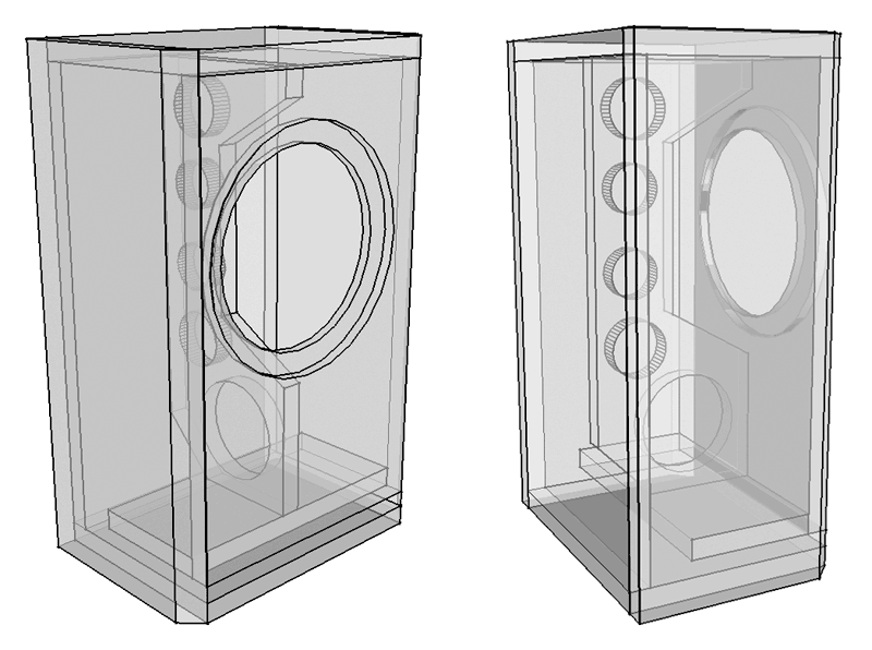
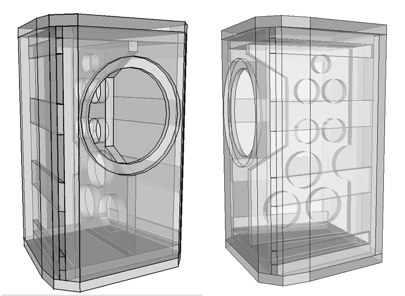
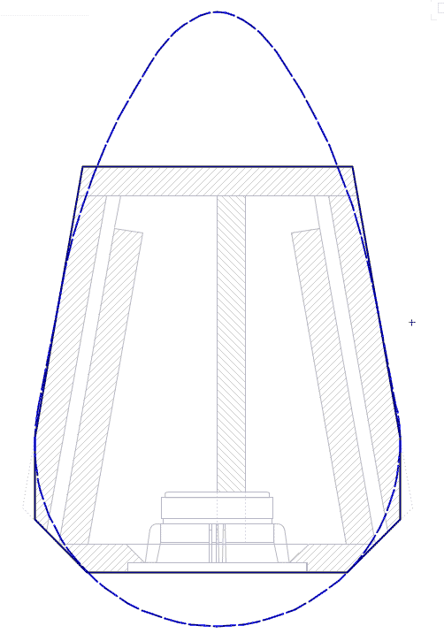
The plan of the shape mimics a teardrop.
dave
In a listenng comparison, experienced and inexperienced listeners both hear a difference between these two box shapes — same driver, same tuning. One a token chamfer on a monley coffin (Golden Ratio shaped) and what bwe call it a Trapezoid despite having 8 sides if the chamfers are included
The plan of the shape mimics a teardrop.
dave
Is one shape preferred or are they equally good but different?hear a difference
I forgot the results part of that post:
The differences were readily heard as a significant reduction in the audiabilty of the box. The CGR box drew attention to itself, whiie image/soundstage was good, it was marred by seeming to “cling” to the box. The trapezoid ‘disappeared” and image/soundstage became better and gained a significantly greater 3D aspect.
Both exist because the trapezoid is much harder to build.
dave
Last edited:
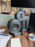
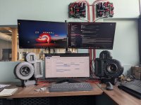
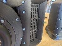
I applied what I learned here to my desktop monitor setup. I can confirm that the imaging of a design meant to heavily reduce diffraction is just unbelievable.
The speakers basically dissappear. I even had one person look behind the screen to try to find a hidden speaker.
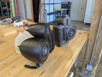
I am quite sold on doing all I can to minimize diffraction. I can 3d model and print about any shape I want now so there's no reason to not apply proper shapes to the speakers.
You can argue all day the benefits of applying dege diffraction VS the work but when the work is just click and print, it really becomes a moot point.
The speakers basically dissappear. I even had one person look behind the screen to try to find a hidden speaker.
I am quite sold on doing all I can to minimize diffraction. I can 3d model and print about any shape I want now so there's no reason to not apply proper shapes to the speakers.
You can argue all day the benefits of applying dege diffraction VS the work but when the work is just click and print, it really becomes a moot point.
Attachments
Well done..
Now time to start the thot experiments on how you reshape the details to get the tweeter closer to the midBass.
dave
Now time to start the thot experiments on how you reshape the details to get the tweeter closer to the midBass.
dave
I'm sure you could do better in the space available. F3 of 36 Hz flat to 31khz. Within a 350mm cube on a desk.Now time to start the thot experiments on how you reshape the details to get the tweeter closer to the midBass.
- Home
- Loudspeakers
- Multi-Way
- Edge Diffraction Testing - Shapes