What is all of that in the left image? All you should have is the end of the probe and the ground clip that's connected into the slot in the probe.
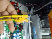
I'm such an idiot, I thought you were referring to the source ground and not the source pin on the MOSFET.
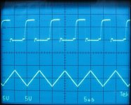
I can confirm it's 10 volts pkpk now. But there's no safe way to attach it the probes ground to the source pin.

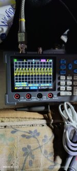
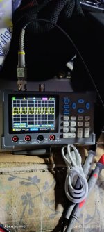
The scope probes typically come with that type of clip for the probe itself. You can hold the ground to take the photo. You can check the rest without photographing them. If you do photograph any more, set the timebase to display only 3 or 4 cycles. The resolution is too low with so many cycles.
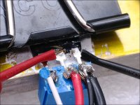
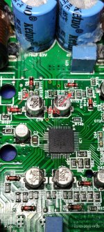
Are these the original part FETs or did some fail?
Has anyone else worked on the amp?
1mil Kapton tape is generally OK for most class D amplifiers.
Are these the original part FETs or did some fail?
Has anyone else worked on the amp?
1mil Kapton tape is generally OK for most class D amplifiers.
3 or 4 cycles? I've only been using a scope for a few months now so I'm still learning the ropes.
I can confirm these are the original FETs.
Yes someone else was working on it but they didn't get anywhere.
Okay.
The only thing I changed was 4 6800 SMD resistors to 8201.
I can confirm these are the original FETs.
Yes someone else was working on it but they didn't get anywhere.
Okay.
The only thing I changed was 4 6800 SMD resistors to 8201.
Okay I get it now.Resistor change?
5 1/2 cycles in the scope image.
Is this your amplifier or are you repairing it for someone else?
Before the amp came to you (before it failed), was it working normally?
With at least 12v feeding the amplifier (no excessive limiting), what is the rail voltage in this amplifier?
Before the amp came to you (before it failed), was it working normally?
With at least 12v feeding the amplifier (no excessive limiting), what is the rail voltage in this amplifier?
I'm repairing it for another technician.
I don't know, I was told it's not working. When I tested it, it comes on but no Audio.
With 12.6 volts going in the rail voltage is +/- 40 volts. The input section op-amp voltages is +/- 14.4 volts. The ICs VCC voltage is 11 volts and VCC2 is 10.4 volts. CSD is 10.5 volts and VSS is 5.4 volts and VAA is 5.7 volts.
- Home
- General Interest
- Car Audio
- Taramps DS 1200X4 output transistors getting hot and amplifier pulling excess current