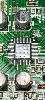
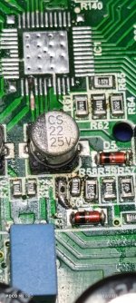
Referring back to the PDF file posted in #96 and figure 15 on page 18. Do these resistors correspond to R2 in that diagram?
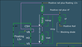
If connected as shown, there is absolutely no reason that the 680 ohm resistor could cause the outputs to run hotter. This circuit is run with 0 ohms in the Rdrop location. At this point, I don't think I'll be able to help any further if they are actually causing heating.
I don't think they're the ones causing it, but with the 8.2K in place in stead of the 680 the amplifier is not as hot.
Could the low voltage VCC be the issue? The other amplifiers I've checked were 14 volts give or take, this amplifier it's all the way down to 11.4 volts.
Also the gate resistors are 4.7 Ohms would replacing them to 10 Ohms make a difference?
Just to let you know I didn't study electronics, what I know is what I've picked up over the years from various places and people like yourself.
So... if you take 2 channels operating at the same (lower) frequency and install the 680 in one channel (8.2k in the other), the 680 channel will run hotter?
The drive signal was 10v when you posted waveforms. That's sufficient. If the drive is dropping significantly, that could cause heating.
I don't know what the regulator for VCC is so I can't know what's normal.
10 ohm gate resistors would likely cause more heating but there are some things that are not obvious. In general, higher resistance will cause more heating but the higher resistance could increase the turn-on time and reduce heating due to very slightly longer deadtime. It can also increase turn-off time which would increase heating. Modifying one channel at a time (for two channels that are otherwise identical) would be the only way to know what the change in gate resistance will do.
VERY few (on this forum) doing this work have any formal electronics training. VERY few are willing to take the time to learn ANYthing that's not directly related to get the next amplifier repaired.

Channels 3-4 don't run hot at all, wether the Rbias is 680 or 8.2K. channels 1-2 are the ones getting hot one more than the other and it's mostly the high side FET. If I remove that channel's FETs the issue jumps to the next channel beside it. If remove that channel's FETs the issue goes over to the other side of the amplifier until all FETs are removed.
The regulator is a TIP 41N.
So I think I will try changing the gate resistors because I already changed the dead time 8.2K resistor to a 12K like the other amplifiers and it's the same issue. The only thing that's different from the other amplifiers is the gate resistors.
I see, I keep a record of what I've fixed and what I did to fix any electronics I've worked. Your website was a huge starting point.
Hello Mr Babin, the amplifier is complete. The technician I was repairing it for says it's regular for those amplifier's to pull that much current while idle.
He tested it and is satisfied with the outcome.
So thank you.
He tested it and is satisfied with the outcome.
So thank you.
Last edited:
I have another one to repair, the IRS 2093 was fried along with a trace, VS4.
Also the technician's power supply I was using is quite finicky it has the coarse and fine dials I think my had bumped it and it went up to 28 volts and killed the 27324 IC that drives the power supply FETs.
Also the technician's power supply I was using is quite finicky it has the coarse and fine dials I think my had bumped it and it went up to 28 volts and killed the 27324 IC that drives the power supply FETs.
Attachments

- Home
- General Interest
- Car Audio
- Taramps DS 1200X4 output transistors getting hot and amplifier pulling excess current