For signal input wiring I usually use two stranded 26awg conductors twisted together for SE connections. Never had an issue with noise.
I have a roll Canare L-2T2S just sitting and figured to give it a try with XA-252.
My question…..
The twisted conductors will connect signal and signal ground between input socket and amp board, but how should I handle the braided shield connection?
https://www.markertek.com/product/l-2t2s-bk/canare-l-2t2s-audio-cable-black-per-foot
for se, shield to gnd, pcb and rca shell
///////
for ball, shield to gnd, pcb and xlr pin1; or by perfect rule - xlr pin1 to case, cable shield open at xlr side, soldered to gnd at pcb, pcb grounded to PSU, PSU having ground lift to case (NTC or whatever)
which one is better, depends of several other details ...... go with simpler, good enough in our sorta semi-pro world
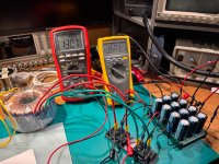
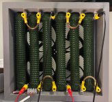

Everything except the bridges (45 C) that had to tiny cooling kept cool. Donut + 8 over ambient, caps stayed as ambient, and the dummy load abt 10 over ambient with the pc fans I installed. Ran it for half a day
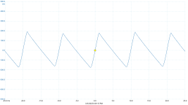
I got my act together and built another 2x40mF C and plugged one of the two 12 vac secondaries to a C-R-C and the other to a C-L-C and the 0V's together. The R and the L (Hammond159ZL) has exactly the same DCR, 0,11 ohms so they drop the same voltage. I putted a probe to each of the outs on the second C banks and took a pic. C-R-C has a remaining ripple of 27,85 mV and the C-L-C a remaining ripple of 3,07 mV, both peak to peak. Very good result of the C-L-C, almost preamp levels.40mF-0R1-40mF
or even better
40mF-2.5mH-40mF
Load same as yesterday, 1,7 A each
Last edited:
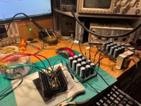
Iron for the win!I got my act together and built another 2x40mF C and plugged one of the two 12 vac secondaries to a C-R-C and the other to a C-L-C and the 0V's together. The R and the L (Hammond159ZL) has exactly the same DCR, 0,11 ohms so they drop the same voltage. I putted a probe to each of the outs on the second C banks and took a pic. C-R-C has a remaining ripple of 27,85 mV and the C-L-C a remaining ripple of 3,07 mV, both peak to peak. Very good result of the C-L-C, almost preamp levels.
Load same as yesterday, 1,7 A each
View attachment 1431029
Iron for the win!
besides smoothing things tremendously, it's also serving as ballast for Drakkar

It catches RF though, needs to be boxed up. Filtered away above 200 kHz. It’s still present when current is off.
And a correction, RMS, not P-P as can be seen on the scales
And a correction, RMS, not P-P as can be seen on the scales
Last edited:
not a problem when you call Mr. Faraday to make a cage
which, incidentally, you have when you cobble everything together
which, incidentally, you have when you cobble everything together
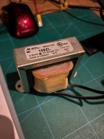
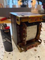
Now I know that a pair of those will give me a clean and sturdy (800 VA in total) +/- 32 volts for applications needing that, and that they can chew 80 mF on first C without complaining.
Next in line will be some cuter EI cores that I suspect can stop at 100-150 VA.
So for those donuts I will need two for the voltage, for the EI’s I might need two for the amps.
Would be nice to put some old Iron from Smaugs stashes to use if I can anyhow.
Note proper bic
Next in line will be some cuter EI cores that I suspect can stop at 100-150 VA.
So for those donuts I will need two for the voltage, for the EI’s I might need two for the amps.
Would be nice to put some old Iron from Smaugs stashes to use if I can anyhow.
Note proper bic
Attachments

Testing my repaired XA 252 channel, I seem to get continuity from the various Q1 and Q2 legs to points on circuit board
that should have continuity. Points at R24, The two tiny SMD caps on either side of Q1 and Q2, but I keep losing track of which leg is what
on Q1 and Q2, facing each other, so "opposite" but after driving myself nuts I do believe I have tested all relevant connections and
am surprised that all seem to work!
Not being the brightest bulb on the DIY porch, if any sharp eyed folks see a test point I could have missed feel free to point them out, much thanks in advance.
I used the schematic at beginning of thread, straight mosfet puck version.
Russellc
- Home
- Amplifiers
- Pass Labs
- Babelfish XA252 / Babelfish XA252 SIT / Babelfish XA252 SET