I cannot see a miscommunication. 47k resistor is considered, we have cartridge//47k thermal noise, we have amp input noise voltage and we have amp input noise current that flows through cartridge//47k to make further noise component. We have usual 3 noise sources that are summed. What is the problem?

OK, sorry for simplified communication. "It is" meant this:
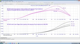
#76 shows quite clearly is that the current source noise issue
input current noise is formed not only by input stage transistors but also by input "47k" resistor (which is outside the op-amp). In a FET input preamps it is dominant, see attached simulation with my version of "passive cooling" denoising (I use 150k/25pF input instead of "standard" 47k/220pF)The cartridge is loaded with 47k//220pF. When the op-amp voltage noise is below 5nV/rt(Hz), it is only and only op-amp input current noise that defines total noise over 20Hz - 20kHz band.
Attachments
Last edited:
Use the Norton equivalent of a resistor with thermal noise and you see immediately that termination resistor thermal noise contributes to the equivalent input noise current of the phono preamplifier, about 0.5869 pA/√Hz when you use an ordinary 47 kohm resistor at 20 degrees Celsius (as opposed to an electrically cold resistance or an unusual termination resistor value). It's more a discussion about accounting than about semantics.
Last edited:
cartridge impedance is much lower than 47k in the main audio spectrum (and effectively shunts 47k resistor), so you must use Gustav Kirchhoff`s laws to measure circuit noise (or simply Microcap 12 as I do) or use a Norton current equivalent as Marcel wrote. That is, in this case "47k resistor creates thermal current noise (4kTB/R) rather than voltage noise."47k resistor creates thermal noise (4kTR*B) rather than current noise.
Last edited:
I was thinking there aren't any other forums where one would find a half-dozen members all of whom have designed the world's best phono pre-amp. 😉
Ed
Ed
Off topic: when you read the Journal of Solid-State Circuits, you see that almost every article features a figure of merit showing that the circuit in that article is the world's best. I sometimes wonder what has taken more time: designing the circuit or coming up with a figure of merit it excels in. 😉
Am I correct in assuming that the best tolerance (of 5% values) caps should go to C8 rather than C7?
Much thanks, as always,
Chris
Much thanks, as always,
Chris
Parts order to Mouser tomorrow evening. We'll send you one when the the PCB version is finished. (First one will look pretty crude inside - perf-board version of dead bug, so not for polite company.)
We're also making a Lipshitz anti-RIAA with 1% tolerance because we don't really trust the version built into the Sound Technology 1200A and the S-T 1700B only goes down to 10 Hz. Good enough for ordinary use but not for this project.
All good fortune,
Chris
We're also making a Lipshitz anti-RIAA with 1% tolerance because we don't really trust the version built into the Sound Technology 1200A and the S-T 1700B only goes down to 10 Hz. Good enough for ordinary use but not for this project.
All good fortune,
Chris
I don't understand the purpose of R3, C4. Are these chosen to guarantee stability of the type OPA1656 opamp, or are they the regular input LPF to deal with RFI, etc. ? Would these particular values be needed with type OPA2134 opamp, a milder device?
Asking because Bob Cordell 1st edition recommends terminating the "transmission line" of interconnecting cables with its characteristic impedance, to minimize peaking and thus possibly RFI. Ordinary coaxes tend towards 50 to 100 R, so could we use 75R for R3, and if so how much C4 (That sounds dangerous!) is needed with OPA2134 speed opamps?
Much thanks, as always,
Chris
R3 and C4 in the circuit of post #58, https://www.diyaudio.com/community/attachments/sriaa2_3-png.1420696/ , are meant to solve stability issues when the op-amp is an OPA1656 and the input is connected to a transmission line of about 1 metre long with a velocity factor of about 2/3 of which the other side gets shorted by a muting switch in the turntable. It also helps for other fast op-amps, it is not needed for op-amps that are too slow to undamp the quarter-wave resonance of the cable. The OPA2134 should be in the latter category.
As you probably guessed (or read in a note on the schematic), it comes from the first 198 posts of this thread, https://www.diyaudio.com/community/...split-from-opa1656-thread.377331/post-6785883 , where JRA heard an enormous bang out of the loudspeakers whenever the muting switch inside the turntable shorted the cartridge at the end of the record. My hypothesis was that the amplifier had a negative input conductance that undamped the quarter-wave resonance of the cable to the amplifier. The cartridge required a low load capacitance, so the idea was to add an RC damper that gives as much conductance around the quarter-wave resonance as possible per unit capacitance. That meant that the RC time constant had to be about 3 ns, and the actual values had to be determined experimentally, keeping a considerable safety margin.
I later also did some calculations on stability versus source impedance, see https://www.diyaudio.com/community/...lity-and-source-impedance.420032/post-7846714
In another thread, someone asked for a variant with higher midband gain, see https://www.diyaudio.com/community/...split-from-opa1656-thread.377331/post-7939733
The split R6 could even be stretched to something like a Nick Sukhov loading. Seems like there would be a small subsonic noise penalty, but hopefully acceptable with modern opamps of low 1/f noise currents. I'm tempted to make R0 and R6 both 100K, so could use some 0u1F "see through jellyfish" MIAL polystyrene caps for C2 that have been hoarded many years.
Much thanks, as always,
Chris
Much thanks, as always,
Chris
Hi Marcel, I need your help with a lower midband gain (30dB) for a RIAA headamp. I'm a beginner in LTspice. Pls have a look at the values for 30dB. Do they look reasonable?In another thread, someone asked for a variant with higher midband gain
Attachments
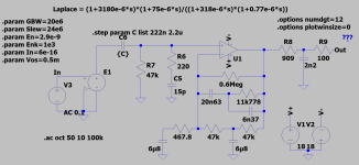
I think you calculated them all correctly for the second-order Butterworth case, but as my equations are only approximate, you get a few tenths of a decibel error here and there anyway.
- Home
- Source & Line
- Analogue Source
- Single-stage active RIAA correction with second- or third-order Butterworth high-pass included