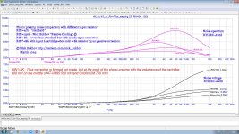
With a 1 Mohm output resistance of the common-emitter stage and a 180 kohm input impedance of the T-network and assuming you have something similar to a Middlebrook or Tian loop gain probe at the cross, I still don't see how a load impedance decrease from 470 kohm to 10 kohm can only cause a 9 dB loop gain drop, unless the first resistor of the DC loop is around 21 kohm, which would be quite small.
Is my assumption that there is a loop gain probe at the cross to the right of the output transistor wrong perhaps? Feedback amplifiers often have different loop gains depending on where you probe.
Last edited:
Yes of course, this is a Middlebrook/Tian loop gain probe that covers both the feedback loop and the external load (and also DC servo), see attached file. I think the slightly strange unusual behavior of the loop gain is due to the unusual T-shaped network (with 'vertical' RC forming 7950 us relatively low 8k2 shunting resistor) of my patented feedback, which in a single net implements 4 time constants without using an additional separate gain stage or an additional network for the rumble filter.Is my assumption that there is a loop gain probe at the cross to the right of the output transistor wrong perhaps? Feedback amplifiers often have different loop gains depending on where you probe.
Attachments

Last edited:
I use in DC servo FET opamp OPA192, so both DC servo resistors are 1 Meg. PS. Thanks for your active cooling idea, I dedicate attached "anticooling" big noise phono preamp test vs passive cooling to your article in EW 10-2003.unless the first resistor of the DC loop is around 21 kohm, which would be quite small.
Attachments
Last edited:
@MarcelvdG
I think this is an interesting design.
Regarding the second schematic in the opening post, could I build this and expect decent performance, or is this 'proof of concept' only?
I'm asking because I'm thinking of building a RIAA equalizer to fit into my turntable and it has a regulated single supply voltage inside (16,5 V). Reason being that I bought a new solid state amp with too high input sensitivities on all input channels and a too high input capacitance for my MM head. Since the amp is new, I don't want to make changes to the inside of the amp (yet). The sensitivity issue for the CD and Tuner inputs I've fixed with voltage dividers (2 resistors) soldered into the RCA plugs to reduce the level of the signals, but for an MM input, I don't think this is feasible. It would also leave the too high input capacitance to be dealt with. So, with an external RIAA amp I could fix both.
Two more questions:
Do you think I could simply use an NE 5532 as OpAmp? I'm not seeing anything mentioned, I think?
I want to reduce A @ 1 kHz to around 30 dB, as my cartridge's output voltage is specified as 5,5 mV and my amp inputs are 150 mV. Is there a clue to what needs to be changed without upsetting RIAA and low roll off behaviour?
Hi Arjen,
I will answer your questions, but it may take a few days. It's toad mating season now, and I am one of the volunteers who help them cross streets.
Best regards,
Marcel
I will answer your questions, but it may take a few days. It's toad mating season now, and I am one of the volunteers who help them cross streets.
Best regards,
Marcel

Excellent work! I'm a member of our local nature preserve and yesterday while rambling through the fields, we ran into some natural ponds full of frogspawn. The ponds had almost dried out because of the dry period we're having. Today we're going back to transplant the frogspawn to another pond that will likely not dry out.
Back on topic 🙂: Your future input is highly appreciated!
Back on topic 🙂: Your future input is highly appreciated!
OK, so I've done some calculations for a different Gain. I hope @MarcelvdG can comment whether I'm correct.
I would need a Gain of 10^(30 + 20 dB / 20) = 316. (This is for an output of 150 mV at 5,5 mV input nominal @ 1 kHz)
DC Gain = 1 + C8/C5
Not wanting to upset the RIAA circuit, I keep C5 = 6n8 -> C8 = 6n8 * 316 = 2,2 uF
1st RIAA pole = R12 x C8 = 3,18 ms -> R12 = 3,18 x 10^-3 / 2,2 x 10^-6 = 1k445 = 1k5 or 1k47
Makes sense?
Besides the NE5532 I would also have the OPA2134 for a build.
Yes, except that 1k43 is just a little closer than 1k47. A disadvantage of such a high value for R12 is that the noise of the feedback network isn't negligible anymore, but it is not dominant either.
NE5532 or NE5532A (variant with guaranteed noise performance) is pretty good for moving-magnet phono amplifiers. On paper, it is not quite as good as NE5534A, but I suspect that the difference is smaller in reality than it seems when you look at the 1 kHz noise specs. That's because the noise current at 1 kHz appears to be largely 1/f noise, and it is mostly the noise current density at higher frequencies that matters.
This should work pretty well. C4 is to be adjusted to whatever load capacitance your cartridge needs, minus cable capacitance.

The main deficiency is a zero at -444172 rad/s that is due to the gain dropping to 1 instead of 0. It causes the gain to level off instead of to keep dropping around 70692 Hz. If it bothers you, you can add an extra first-order low-pass filter with a time constant of 2.2514 us after the amplifier.
I shifted the corner frequency of the subsonic filter to 16 Hz because it was explained in another thread that turntables often have a nasty arm resonance around 10 Hz. C7 and C8 should be film capacitors, definitely not class 2 ceramic capacitors, and C8 should be reasonably accurate. That probably means +/- 5 %, as 2.2 uF capacitors with smaller tolerances are rare.
NE5532 or NE5532A (variant with guaranteed noise performance) is pretty good for moving-magnet phono amplifiers. On paper, it is not quite as good as NE5534A, but I suspect that the difference is smaller in reality than it seems when you look at the 1 kHz noise specs. That's because the noise current at 1 kHz appears to be largely 1/f noise, and it is mostly the noise current density at higher frequencies that matters.
This should work pretty well. C4 is to be adjusted to whatever load capacitance your cartridge needs, minus cable capacitance.
The main deficiency is a zero at -444172 rad/s that is due to the gain dropping to 1 instead of 0. It causes the gain to level off instead of to keep dropping around 70692 Hz. If it bothers you, you can add an extra first-order low-pass filter with a time constant of 2.2514 us after the amplifier.
I shifted the corner frequency of the subsonic filter to 16 Hz because it was explained in another thread that turntables often have a nasty arm resonance around 10 Hz. C7 and C8 should be film capacitors, definitely not class 2 ceramic capacitors, and C8 should be reasonably accurate. That probably means +/- 5 %, as 2.2 uF capacitors with smaller tolerances are rare.
I've looked into ways to reduce R12 for an amplifier with a gain of about 30 dB without needing awkward values for C5 and C6 and without making the RIAA zero and second pole less accurate. This set works well, but R12 is not reduced a lot:
R0 = 576 kohm
C2 = 1.5 uF
R6 = 105 kohm
R2 = 100 kohm
R1 = 4.7 kohm
C1 = 47 uF
R7 = 732 kohm
R8 = 23.2 kohm (or 23438 ohm; the zero and second pole are theoretically very accurate with 23438 ohm and infinite loop gain)
C6 = 3.3 nF
C5 = 10 nF
R11 = 47.5 kohm
C7 = 4.7 uF
R10 = 47.5 kohm
R12 = 953 ohm
C8 = 3.3 uF
C3 = 47 uF
R5 = 11 kohm (assuming that the load will typically be 47 kohm; not that it matters much)
The extra zero ends up at -442140 rad/s, so the extra first-order low-pass filter, if any, has to have a time constant of 2.2617 us.
For completeness:
Although I haven't drawn any power supply decoupling or any power supply connections at all, the op-amp supply pins obviously need to be connected and decoupled.
The pin numbers shown on the schematics are only correct for the second op-amp of most dual op-amps.
Although I haven't drawn any power supply decoupling or any power supply connections at all, the op-amp supply pins obviously need to be connected and decoupled.
The pin numbers shown on the schematics are only correct for the second op-amp of most dual op-amps.
@MarcelvdG
Marcel, I've started building the pre-amp in post #148, but I have a few more questions:
Marcel, I've started building the pre-amp in post #148, but I have a few more questions:
- In this kind of design, in commercial units, I often see a small cap. (330p/470p) from the Inverting to Non-inverting input of the OpAmp. What is this for, and would it be wise to add one here as well?
- I've also noticed in some commercial designs a 100 Ohm resistor feeding from the output of the OpAmp into the RIAA correction circuit (or placed between the RIAA correction circuit and Non-inverting input of the OpAmp). I have the same question on this.
- For R5, why have you chosen 10k or 11k? In commercial designs I often see 100k. You say it doesn't matter much, but you must have chosen it for a reason.
- I would like to add a capacitor on the output to limit the bandwith. I have 6,8 nF available. With 100 R output resistance and some cable capacitance this would mean a corner frequency of around 200kHz. Sounds reasonable, right?
In this kind of design, in commercial units, I often see a small cap. (330p/470p) from the Inverting to Non-inverting input of the OpAmp. What is this for, and would it be wise to add one here as well?
Presumably to filter RF interference. It may cause stability issues, particularly when the turntable has a muting switch. I wouldn't add it, but if you want to, you will have to measure step responses with various source impedances to ensure it doesn't cause trouble.
R3 has the same purpose, by the way. It filters RF interference at the input together with C4, without the potential stability problems.
I've also noticed in some commercial designs a 100 Ohm resistor feeding from the output of the OpAmp into the RIAA correction circuit (or placed between the RIAA correction circuit and Non-inverting input of the OpAmp). I have the same question on this.
I don't know the answer to this question.
For R5, why have you chosen 10k or 11k? In commercial designs I often see 100k. You say it doesn't matter much, but you must have chosen it for a reason.
It's a matter of unreasonable perfectionism. The zeros of the high-pass filter are not exactly in the origin, meaning that the slope of the filter decreases somewhere far in the subsonic region. The high-pass filter zero that is furthest from the origin is corrected for by C2, R2 and R6. When R5 is 11 kohm and the load is 47 kohm, C3 corrects for another high-pass filter zero. The difference is only noticable below 0.38 Hz, which is why it is unreasonable perfectionism.
If you should want to increase R5 much, you will also have to decrease C3 to keep the settling time at start-up reasonable.
I would like to add a capacitor on the output to limit the bandwith. I have 6,8 nF available. With 100 R output resistance and some cable capacitance this would mean a corner frequency of around 200kHz. Sounds reasonable, right?
When you increase R4 to 332 ohm, or maybe 309 ohm to have margin for cable capacitance, and add the 6.8 nF, you correct quite nicely for the ultrasonic zero (or in normal English, you actually improve the RIAA correction) and you reduce the load on the op-amp.
Thanks. I might go for a low 300 Ohm for R4, if I have this in my collection. The rest I will leave as you have designed it.

- Home
- Source & Line
- Analogue Source
- Single-stage active RIAA correction with second- or third-order Butterworth high-pass included