The 0.39% is the limit measurement of my scope. Distortion could be less.I consider this significant. My speakers in my living room play nearly the full spectrum under 1% at normal volumes. A 0.39% increase in distortion would be significant. Let me show you the graph
In your graph the fundamental plot was missing,

Hi, sorry I didn't understand you ment some specific crossover. My post was to encourage anyone to figure out how a transducer works so it's easy to make a crossover for what ever purpose, juggle with impedance as needed, in general. Discussion prior was about what inductor to use and how it's DCR affects, possible distortion stuff relating to it and so on, with impression many participants including OP wasn't sure how the stuff plays out.Well, that is not the magical crossover, but only additional LCR series circuit to compensate the woofer impedance rise at the resonant frequency ("conjugate loading" by KEF, many years ago).
Sorry, but 1.1 mF (!!!) condenser, 3.9 mH inductor and 50W resistor are very expensive addition to the crossover, only to make current drive usable! Besides, you didn't post the crossover schematic (as asked!), because current drive will mess up the frequency response of crossovers posted here before.
Distortion improvement depends on how good a driver is. Point is, if one knows how this stuff works they can utilize any impedance manipulation technique if it benefits. There is no point use bad solution, as you point out.Expensive juggling with additional components and unnecessary wasting amp power on series resistor, for a questionable improvement on distortion.
The only logical and economically justified solution is amplifier with complex negative feedback to make it to have low output impedance at low frequencies and high output impedance at mid and high frequencies. But that knowledge is out of ability of 99.999% of all DIY folks.
Anyone can build a bridge, but only and engineer can build a bridge that barely stands.I like to engineer the components to squeeze them, knowing the limits and the effects, rather than just use an expensive solution, where no engineering is need.
Its not the worst thing I've ever seen but I'll be honest, I think you try using a different program. This makes the tweeter kind of useless.OK... just for one last ditch effort, try this. I won't tell you what my sim shows, but try it at all angles between plus or minus 30 degrees.
Hi,
From 200/300Hz up, THD drops to -50dB and the woofer is cut around 800Hz. This is an important audio range for sure and you've got low distortion.
Despite of that, using a gapped iron core with effective permeability around 10, from my experience, it will not make a relevant difference versus the air core.
Important: If you plan to buy this iron core inductor from a vendor, you need to make sure how much it distort. I took a look on the JANTZEN and Dayton, for example, and I didn't find THD information and they don't indicate how much margin to saturation each inductor has in terms of max current. They mention max power but we don't know how they engineered that maximum current. They should tell us the current value where the knee starts (e.g. 10A @ knee and you will be using 6A max, so ok!) and they should say, at low levels, how much THD is expected for a certain impedance. It all depends on how they engineer their inductors. For toroidal ones (C-Core) there is a permeability chart indicating 70, which I think is too much if it is what they are using - it's not so clear.
Two options:
-Build your own inductor by engineering it as I suggested (I can help you if you want) and confirm with measurements. In this case, even if the results are not ok, you don't waste much material, cause you can reuse it for another project - just some cooper wire and cheap iron core. And if you really enjoy playing with these things - I like a lot and it is part of the fun!
-Or you can buy an off the shelf iron core unit, if it is cheap and easy to order, and make the measurements with your system.
If it is ok, still getting -50dB, buy another one and build your crossover.
Dayton I-Core units are cheap (US$8.50) and here we know there is a lot of air gap (so effective permeability will be low, which is good for THD), since the magnetic circuit is not even closed - it's just a rod. Maybe this one is worth a try if we don't get any further information about other vendors.
I never used any off the shelf inductors, so I cannot guarantee anything here.
It's good that each one gets his/her own experience about polemical subjects. Somone say one thing, other people say another thing. By measuring and hearing yourself, you'll get your own and final opinion.
Yeah, I might have to do some experimentation to see if I can measure it, or hear it.-Build your own inductor by engineering it as I suggested (I can help you if you want) and confirm with measurements. In this case, even if the results are not ok, you don't waste much material, cause you can reuse it for another project - just some cooper wire and cheap iron core. And if you really enjoy playing with these things - I like a lot and it is part of the fun!
-Or you can buy an off the shelf iron core unit, if it is cheap and easy to order, and make the measurements with your system.
If it is ok, still getting -50dB, buy another one and build your crossover.
Dayton I-Core units are cheap (US$8.50) and here we know there is a lot of air gap (so effective permeability will be low, which is good for THD), since the magnetic circuit is not even closed - it's just a rod. Maybe this one is worth a try if we don't get any further information about other vendors.
I never used any off the shelf inductors, so I cannot guarantee anything here.
It's good that each one gets his/her own experience about polemical subjects. Somone say one thing, other people say another thing. By measuring and hearing yourself, you'll get your own and final opinion.
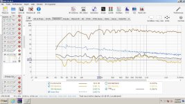
Here's looking back at a design. The woofer itself is the blue line. The yellow line is the full system response with crossover in the network. This was crossed at 350hz 2nd order using an iron core.
They are not exactly SPL aligned but pretty close.
Woofer distortion
System Distortion.
Of course this isn't totally apples to apples but, it is higher distortion with the XO in place than without.
Yes, it's a bit higher with the filter depending on the frequency range.
Between 100Hz and 200Hz, no filter has an average (by "eye") of around 0.3/0.4% and with filter around 0.6/07%.
At exact 50Hz, both have 1.5%.
Acoustic variations are so huge, when looking at specific frequency, due to reflections, mic position, cancellations, distance etc when measuring speakers, that I don't consider this difference much high and detectable when listening - you'll be able to tell us.
Apples to apples only if you build an air core to compare with an iron core with the same inductance.
Keeping everything the same, speaker/mic position, volumes, capacitors etc, and just swapping inductors (with the similar DCR).
Extra work, but it is something for a life. From this test on, you will have your final opinion.
Good test of air core vs iron core distortion:
https://hificompass.com/en/projects/experiment/test-couple-iron-core-inductors
https://hificompass.com/en/projects/experiment/test-couple-iron-core-inductors
Plenty of very expensive speakers start reaching 3% distortion at 8 to 11 volts
So the inductor nonsense is so far into nonsense it is ridiculous.
18 gauge 2.5 to 5mH will use laminated silicone steel core with everyday size around 3 inches
Which is more than good for 5 to 8 amps for saturation.
Hence why you dont give a hooty tooty
70 watts wont do dingle to a 250 watt coil, and the real world 15 to 25 watts really do nothing
If you even managed to get 16 volts into the system ( you wont) with basic to expensive everyday 83 to 87 dB home audio speakers.
The coil is no where close to saturation and the 10% or more actual speaker distortion is far far far more audible than a iron core inductor.
You dont need 500 to 800 watt coils in a home audio system, and spacing the coils apart for a huge bundle of noise antenna wire. Is ridiculous.
Even jumping to 600 watt 15 gauge coils is such a laugh fest, Most pro audio speakers dont even touch those real world levels.
And if they do Guarantee = Active crossover.
Youll hit way more speaker distortion with 100 watts before the coil even give a hoot.
The bigger and more expensive the better right? just make a Youtube video make up nonsense and repeat Quality, blah blah Quality 50 times
and bang you sold the world...LOL.
I feel sorry for anybody spending more than 20 dollars for a woofer coil and a midrange never moving more than 1mm with 400 dollars of wire coils
buah hah hah hah = sorry.
Even Wharfedale had to Triple their prices for " Higher Quality" crossovers dealing with brain washed after market nonsense driving up crossover
prices. Now you cant sell a system without 600 to 1000 watt coils for a "100 watt" speaker that never gets more than 30 to 60 watts it whole life.
People wanna pay more money. Put 6 thousand dollar racing tires on your 30 to 65 mph daily commuter Nissan Versa. Woo Hoo
those 20 mph turns will never be the same " Quality"
Last edited:
Going back in time ...
after buying my high power 'super amp', I proceeded to make the highest power speakers I have ever built.
With appropriate spacing, I used TWO 6.5mH 18 gauge iron-cores in parallel giving me the 3.25mH needed.
This gave me totally high power and low DCR inductors 🙂
after buying my high power 'super amp', I proceeded to make the highest power speakers I have ever built.
With appropriate spacing, I used TWO 6.5mH 18 gauge iron-cores in parallel giving me the 3.25mH needed.
This gave me totally high power and low DCR inductors 🙂
Basically to beat the Series resistance of a Laminated Steel I core at 1mH 14 gauge( .19 ohms) = 6 dollars
Which has very little " stored energy" the magic word for nonsense youtubers
You would have to jump up to a 12 gauge ribbon air coil = 350 dollars
And the tolerance for the air coil might be still in the 5 to 6% tolerance
When a 6 dollar coil can be within 3% .....LOL
Do you wonder why now a " Air Coil " with low DCR is the " best" coil according to GR research
Your credit card getting raped. Basically your system is already at 3 to 5% distortion the coils is at 0.008 to .018%
According to them you dont want " Iron Core" for highs, But the actual distortion tests shown by perrymarshall's link
Is completely opposite behavior. And the distortion ratings basically the same for both.
The link shows even higher DCR air coils the efficiency is actually rather poor, and they will pick up more noise and crosstalk in reality.
Should I waste my time talking about " 250 volt" capacitors used for systems seeing no more than 8 to 20 volts = NO
Do we know why real companies use " cheesy parts" because the Quality is the = same
Last edited:
Where some see wire to make a coil from
View attachment 1419129
Others see a pre-formed coil.
I have put them in series, and even cut the former away for snug cores. I'm yet to send my own bobbin, but I'm sure a small opp wouldn't mind.
View attachment 1419129
Others see a pre-formed coil.
I have put them in series, and even cut the former away for snug cores. I'm yet to send my own bobbin, but I'm sure a small opp wouldn't mind.
Moral of the story:
1. DC resistance of air core inductors is much higher than iron-core inductors, decreasing woofer sensitivity/efficiency and increasing woofer Qts parameter.
2. Distortion of laminated iron-core inductors is always below 0.1% THD, even with the lowest cost inductors and at ridiculously high current/wattage. Quality brands laminated iron-core inductors have below 0.05% THD, even at ridiculously high current/wattage.
3. Cost of air-core inductors is much higher than iron-core inductors, for the same value of mH.
4. Using air-core inductors for woofers is just stupid. Use laminated iron-core inductors for woofers!
Last edited:
Good test! It matches what I'm measuring. Note that they used iron core based in just an "I" core or a laminated rod. So, a lot of air.Good test of air core vs iron core distortion:
https://hificompass.com/en/projects/experiment/test-couple-iron-core-inductors
When we say "iron core" for audio inductors, we must understand that it is actually "air gap iron core",
If we build an inductor like we build a transformer, with no air gap and with tight closed magnetic circuit the result is in fact horrible high distortion cause we really feel (listen) all the non linearities of the BxH iron curve.
But an inductor for audio has gap or even just a rod, where the magnetic field doesn't even close.
It's a mixture of air and iron, and the "dose" of iron and air will define que amount of distortion and efficiency (wire cooper reduction) you get.
From 100% air to 100% iron, you can find a good balance around effective permeability between 10 and 20.
Just use the right dose, it's not rocket science.
It does make it a super tweeter I guess. Doesn't everybody hear to 30k? There are angles that the mid, and tweeter sum flat. I question whether someone working at a desk would notice any difference when they move, if there's a notch at 15k.Its not the worst thing I've ever seen but I'll be honest, I think you try using a different program. This makes the tweeter kind of useless.
View attachment 1419643
On the other hand, if you were ten feet away, sitting on a couch, you would be hearing a nice on axis, combined with some room reflections with different arrival times. Crossing lower for that use is probably just as good, although some builders seem to like keeping the x-over outside of certain ranges. You know, the guys building single driver designs. Most of those designs probably don't make it to 12k. (I'm just guessing, not intended as an insult. ) Last I checked, I think I could hear 13k, but that was maybe 10 years ago, and not a precise test. Maybe I'll check again using REW to generate the sweeps.
This x-over uses a reasonable amount of parts, and any amp should like the impedance.
I really don't know why our Sims don't quite match. The software I use, is free, and probably used by thousands of builders. For my own designs, I usually don't use Sims at all. I find posting Sims on the forums, using files supplied by others, to be quite entertaining.
I did recently try making my own frd files for a center channel speaker. It was kicking my a$$ trying to get what I wanted by trial and error. The woofer response made it a challenge. I made a sim using my frd files, a factory impedance file for the woofers, and a similar tweeter zma file from a different tweeter. On the tweeter, there was so much padding that the filter only saw a flat impedance anyway. The sim was pretty accurate. I made a few changes, and continued by trial and error to get a smooth off axis response that was actually my intended listening axis of about 20 degrees. After four nights of use, I like it a lot.
Since you are discussing coils here, I have the distortion measurements of my center. It's not a terribly loud sweep, but I have tested louder. I can't find a loud sweep at the moment. Maybe later. The dashed blue line is the noise floor. The coils used are nothing special, and the woofer is 4 ohms. Crossover uses only two coils.
I have lots of both types of coils, and can measure them pretty easily if you would like. This speaker is crossed to a sub, but the woofer can play much lower.
What frequency range are you concerned about the distortion? Below 80hz?
Attachments
Last edited:
- Home
- Loudspeakers
- Multi-Way
- Air Core vs Iron Core - Sensitivity