I agree with Ron, the white line is not at -40dB or further, and is between -35 and -40, making it just over 1%.
-40 = 1%
-50 = 0.5%
-60 = 0.1%
That said, the Jantzen C-Coil should be another alternative not yet mentioned.
-40 = 1%
-50 = 0.5%
-60 = 0.1%
That said, the Jantzen C-Coil should be another alternative not yet mentioned.
Hi,
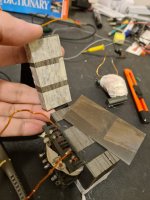
I made some electrical measurements in an iron core test I have here just ro demonstrate what I mean.
This is a first order filter - just the inductor and a resistor (3.9ohm).
I inserted the coil in the iron core using different gaps to achieve the following inductances.
uR = relative permeability - it's how much you will multiply the air inductance.
All measurements done with 1Vrms over a resistor of 3.9ohms.
The idea here was not to test the saturation level, but the distortion at low levels as mentioned during the conversation.
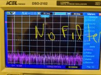
0.134mH (uR=0 - Air Core)
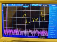
1mH (uR=7.4)
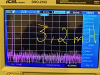
3.2mH (uR=23)
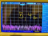
5.4mH (uR=40)
We see that for "no filter" and filter with uR=7.4 (1mH), there is no visible difference at least with my setup - 8-bit scope, sinewave generated by a smartphone and a class AB amp. There is almost 50dB between fundamental and 3rd harmonic.
Increasing to uR=23 (3.2mH), we start to see 3rd harmonic poping up, but still almost 50dB below.
Increasing to uR=40 (5.4mH), we clearly see degradation and less than 40dB. I wouldn't use this config.
For me, I feel safe to use between uR=10 to 15 combining with Ipeak way below saturation (60% for example).
We have to meet both conditions.
I made some electrical measurements in an iron core test I have here just ro demonstrate what I mean.
This is a first order filter - just the inductor and a resistor (3.9ohm).
I inserted the coil in the iron core using different gaps to achieve the following inductances.
uR = relative permeability - it's how much you will multiply the air inductance.
All measurements done with 1Vrms over a resistor of 3.9ohms.
The idea here was not to test the saturation level, but the distortion at low levels as mentioned during the conversation.
0.134mH (uR=0 - Air Core)
1mH (uR=7.4)
3.2mH (uR=23)
5.4mH (uR=40)
We see that for "no filter" and filter with uR=7.4 (1mH), there is no visible difference at least with my setup - 8-bit scope, sinewave generated by a smartphone and a class AB amp. There is almost 50dB between fundamental and 3rd harmonic.
Increasing to uR=23 (3.2mH), we start to see 3rd harmonic poping up, but still almost 50dB below.
Increasing to uR=40 (5.4mH), we clearly see degradation and less than 40dB. I wouldn't use this config.
For me, I feel safe to use between uR=10 to 15 combining with Ipeak way below saturation (60% for example).
We have to meet both conditions.
Attachments

Ask Wolf_teeth if PCD is accurate, in general. He would know better than me I think.
Last edited:
@ron68 What fundamental frequencies are you measuring at to derive those FFT plots?
The discrepancy also resides with the type of load being presented to the inductor ie. phase angles, non-linear EMF coming back from driver Le, etc. A simple resistor won't tell the whole tale.
The size and type of core also makes a difference, but in a way you're already presenting this. It would narrow down variables a bit more using some typical available iron core inductors. Of course the laminated steel cores will distort the least based on my experiences. Sintered ferrite is the worst core material, distorting up to 10% in smaller size cylindrical coils at frequencies around the lowest impedance area of the curve.
Do you guys test distortion at over 100dB? I thought the mic might distort some past 97dB or so.
Whats the benchmark for THD measurements?I would build a cheap iron core (or buy an entry level one), with enough cross area, and measure THD with and without it at several levels (low, medium and high SPL). Just keep uR<10 (relative permeability) - this is 10x gain so you still save a lot of cooper and keep DCR low.
If you see relevant difference, then go for an air core and measure THD again to compare, cause inserting a filter changes the behaviour.
That's what I did for some speaker I've built.
That last graph I showed you was the near field. The far field distortion is much lower. Lower than your stated threshold for the inductor making a difference.
Is it far field at a certain SPL?
Have you bought from US Coils before?
I have gone through their website a couple times and the most I see of anything is them having only 1 in stock. Everything else is "available on backorder"
I ordered from erse.com, unfortunately the owner passed away and the company was sold , Chinese company or not ? on the website it says “ We produce high quality coils
that are wound right here
in the USA with high purity
Copper Wire sourced from
USA suppliers”
The out of stock items dont worry me, shoot them an email.
that are wound right here
in the USA with high purity
Copper Wire sourced from
USA suppliers”
The out of stock items dont worry me, shoot them an email.
Hi!@ron68 What fundamental frequencies are you measuring at to derive those FFT plots?
The discrepancy also resides with the type of load being presented to the inductor ie. phase angles, non-linear EMF coming back from driver Le, etc. A simple resistor won't tell the whole tale.
The size and type of core also makes a difference, but in a way you're already presenting this. It would narrow down variables a bit more using some typical available iron core inductors. Of course the laminated steel cores will distort the least based on my experiences. Sintered ferrite is the worst core material, distorting up to 10% in smaller size cylindrical coils at frequencies around the lowest impedance area of the curve.
I swept frequencies around the Fc of the filter formed by these inductances and the result didn't change much,
What really matters is how much you push with effective permeability, in other words how much you multiply the air coil inductance.
That's why I stress that iron core must be well engineered.
It's not a matter of air versus iron core, but air versus how someone engineered the iron core for a specific condition.
Since I wanted a comparative test with everything else constant, I chose 90Hz (not much criteria) and fixed 1Vrms at the resistor making the adjustments every time I changed the inductance.
Sure the real speaker load changes things a lot. I can grab a woofer and repeat the test.
This core, as the others I use in my speakers, is a regular laminated steel for 60Hz transformer.
Since my idea is limit the use of this core for woofer, I think it's ok.
And yes, ferrite is much more limited since its B saturates at around 0.3T while the laminated steel can go up to around 1.3T.
For mid-range and tweeter, sometimes you can use ferrite, as long as you check the maximum current in order to not saturate.
Could we assume then, that at around 599 Hz the current would be higher since the impedence at 500 would normally be lower than st 90 Hz? And also assume that it would saturate faster?Since I wanted a comparative test with everything else constant, I chose 90Hz (not much criteria) and fixed 1Vrms at the resistor making the adjustments every time I changed the inductance.
I don't know about specific THD benchmarks. Let's see what others comment.Whats the benchmark for THD measurements?
That last graph I showed you was the near field. The far field distortion is much lower. Lower than your stated threshold for the inductor making a difference.
Is it far field at a certain SPL?
My point is how much distortion the iron core will add to your system and if it is worth to spend money on air inductors in your case.
It's worth to test and get real measurements (with air or with iron).
In my measurements, it made no difference, since THD of woofers were varying from 0.5% to 3% or even more depending on the frequency at 80cm distance.
If THD inserted by inductor is below 48dB (0.39%), it is not worth in my case.
When engineering the inductor, there are 3 parameters to check:Could we assume then, that at around 599 Hz the current would be higher since the impedence at 500 would normally be lower than st 90 Hz? And also assume that it would saturate faster?
1. Maximum peak current must be way below the saturation limit in any power or frequency condition. This is the first condition to be met, buy selecting the proper cross section area and core material. For example, in one of the speakers I built, max peak current was 10A, so I selected a core that starts to saturate around 15A.
2. Maximum relative/effective permeability. As shown above, I use around 10 at maximum. This will limit the distortion created by the iron non linearity and hysteresis of BxH curve. And this is simple. If you need 4mH, you build a 0.4mH air core inductor. Then, you adjust the gap to reach 4mH.
3. Resistance (DCR) and heat.
This quick test I posted was to demonstrate how much distortion we have in low levels (250mW) using iron core, cause someone mentioned above that this could be a problem overlooked by people that only think that distortion only occcurs in saturation condition.
And he is right, we have to think about the two conditions.
If you push too much effective permeability, distortion occurs even at very low levels.
I consider this significant. My speakers in my living room play nearly the full spectrum under 1% at normal volumes. A 0.39% increase in distortion would be significant. Let me show you the graphIf THD inserted by inductor is below 48dB (0.39%), it is not worth in my case.
Attachments
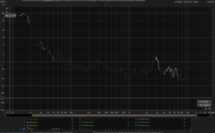
Yes, I think my distortion measurements are pretty useless if we don't know the benchmark. Here is that woofer far field. Pretty darn good for $74I don't know about specific THD benchmarks. Let's see what others comment.
100% you called this one. That fixed that impedence dip.Tweeter padding could be modified as well, series resistor belonging before filter and parallel part modded to match,
thereby preventing the 5 khz dive.
depends on which measurement we go by. Here is the far field measurement. This was taken a quite a high volume level.I agree with Ron, the white line is not at -40dB or further, and is between -35 and -40, making it just over 1%.
-40 = 1%
-50 = 0.5%
-60 = 0.1%
That said, the Jantzen C-Coil should be another alternative not yet mentioned.
Yup, going to do that. Maybe they make them to order.I ordered from erse.com, unfortunately the owner passed away and the company was sold , Chinese company or not ? on the website it says “ We produce high quality coils
that are wound right here
in the USA with high purity
Copper Wire sourced from
USA suppliers”
The out of stock items dont worry me, shoot them an email.
OMG !!!
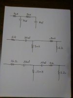
This XO must surly 'win the prize' for > Most Inductors Used.
I have never seen anything quite like it 😎
Many condenser measurement microphones are pretty linear to 115 dB, assuming they have decent supporting circuitry. Some up to the mid 120's. Beyond the 120's typically requires a more dedicated high SPL mic.I thought the mic might distort some past 97dB or so.
Last edited:
- Home
- Loudspeakers
- Multi-Way
- Air Core vs Iron Core - Sensitivity