1.2V is a reference value.
You might have to retrim once you have soldered the power devices and let them warm up on the heatsink.
In our final build, the bias current starts at 0.5A, and ends more than 0.8A after 45 minutes.
You can easily measure the bias current as DC voltage across the 1R power resistors.
How much it fits depends on the size of heatsink, and what insulator you use.
So my values are also for reference only.
As you have installed trimpots on the bypass current source, you can easily adjust both bias and output DC with them.
Once you are happy with the final adjustments, replace them with fixed resistors.
Build the speaker protection before connecting to speakers.
😊
Patrick

Tiny Crafts Romania
Hiraga class A amplifier + Topping D90III Sabre + SB Acoustic

Hiraga class A amplifier + Topping D90III Sabre + SB Acoustic
Tiny Crafts Romania
Hiraga 8W “Le Monstre” on the bench test

Hiraga 8W “Le Monstre” on the bench test
Hiraga 8W “Le Monstre” on the bench test
Original version with original components,
Or 2024 version with modern components and CCS bypass ?
Patrick
Is there any proven advantage to using this beyond the theory of the original design? Especially using the.CCS bypass instead resistor bypass?Or 2024 version with modern components and CCS bypass
Last edited:
I honestly tell you that I didn't expect my work to be seen by so many people. Anyway, I'm glad that I managed to contribute with examples worthy of consideration in this field. Examples that others can take inspiration from. And please, feel free to do so. If you like something from what I did,...borrow.
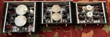
The two examples of the Hiraga amplifier presented by our colleague in the above posts are built by me. In the meantime, the third one has appeared. In the attached picture I want to present all three of them next to each other.
The two examples of the Hiraga amplifier presented by our colleague in the above posts are built by me. In the meantime, the third one has appeared. In the attached picture I want to present all three of them next to each other.
Attachments
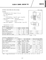
What is the Y grade for the 2sk170/j74? I never saw anything more than GR, BL and V grade for these parts datasheets.
SB
SB
My attempt at optimising the layout, wire lengths... not Hiraga - an AlephJ with some mods.

... keeping the fully shielded and potted toroid happy:

... keeping the fully shielded and potted toroid happy:
Last edited:
From the 1983 catalogue:What is the Y grade for the 2sk170/j74? I never saw anything more than GR, BL and V grade for these parts datasheets.
SB
Attachments
EUVL
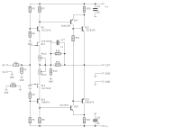
Hiraga Le Monstre Revisited 2024.
""The open loop gain, just like the Pass F5, is load dependent. With 4R load, this is halved compared to
8R. To compensate for this, one could reduce the gain by increasing the 10R feedback resistor to
20R. The output impedance is still something in the order of 0.7R. So the speaker should have
relatively flat impedance over the audio band.""
I change the resistor gain also in my Αlpha Nirvana 39 Ver 4R from 820Ω to 1.8Κ everything goes better.
I do not know.Original version with original components,
Or 2024 version with modern components and CCS bypass ?
Patrick
Someone asked about our Didden Super Power Regulator.
We developed the regulator in 78xx/79xx format for headphone amps years ago.
www.diyaudio.com/community/threads/the-dao-se-all-fet-class-a-zgf-headphone-amplifier.225577/post-4241321
Our version of the Didden regulator differs from the original in many aspects and in component choice. Otherwise it will never fit into the 11x35mm. Jan knows about it, he actually has the first pair ever made. It is never published, as promised.
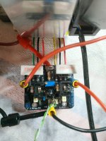
If you just want to make a high power Didden, the simplest way is to use the standard Didden and try to replace the pass device with a high power Darlington. We built this using discrete transistors, as you can see in the photos. In our case, this is the only change.
But I can't guarantee that it works with the original circuit. Our version has enhanced stability, even for low current. So we can use any fancy cap we want at the output, including those huge snap-in 10,000uF caps in the photos.
www.diyaudio.com/community/threads/hiraga-le-monstre-2024.413301/post-7763951
If you believe in Fran's ears, and those of his friends, you don't need them for the Le Monstre.
If you must, you can also use the one published by Grunf, or that sold by Belleson.
www.diyaudio.com/community/threads/hiraga-le-monstre-2024.413301/post-7700003
https://belleson.com/oc/en-gb/superpower/sphp?route=product/category
Patrick
We developed the regulator in 78xx/79xx format for headphone amps years ago.
www.diyaudio.com/community/threads/the-dao-se-all-fet-class-a-zgf-headphone-amplifier.225577/post-4241321
Our version of the Didden regulator differs from the original in many aspects and in component choice. Otherwise it will never fit into the 11x35mm. Jan knows about it, he actually has the first pair ever made. It is never published, as promised.
If you just want to make a high power Didden, the simplest way is to use the standard Didden and try to replace the pass device with a high power Darlington. We built this using discrete transistors, as you can see in the photos. In our case, this is the only change.
But I can't guarantee that it works with the original circuit. Our version has enhanced stability, even for low current. So we can use any fancy cap we want at the output, including those huge snap-in 10,000uF caps in the photos.
www.diyaudio.com/community/threads/hiraga-le-monstre-2024.413301/post-7763951
If you believe in Fran's ears, and those of his friends, you don't need them for the Le Monstre.
If you must, you can also use the one published by Grunf, or that sold by Belleson.
www.diyaudio.com/community/threads/hiraga-le-monstre-2024.413301/post-7700003
https://belleson.com/oc/en-gb/superpower/sphp?route=product/category
Patrick
Last edited:
Looking to build a Hiraga LM, the 8w version as my speakers have over 9xdB SPL
Trying to make a frankenstein version as I want to use CPU coolers for the 4 transistors and SMPS power supply
Does anyone used SMPS or CPU coolers for it?
Also what's the best voltage to run it ( the 8w version?) as I read various materials going from +/-12V to +/-15V
As far as I understood the 8W version needs arround 60W of power per chanel - why everyone goes for such big transformers? Just a reserve?
Thank you!
In this thread, we tried to follow the original as much as possible, given today's circumstances.
We have explained in detail the changes we made, and what consequences they might have, in measurements and listening.
For many other variations of the LM, the original thread is probably more interesting for you :
www.diyaudio.com/community/threads/hiraga-le-monstre.5462/page-123#post-7973070
Patrick
I was asked whether we still have boards, etc.
Fran said that we still have one kit left :
www.diyaudio.com/community/threads/gb-for-hiraga-le-monstre-2024.416424/
We also have bare boards, and one spare pair of Le Monster Modern fully built and tested.
Those interested can contact him by PM.
Patrick
Fran said that we still have one kit left :
www.diyaudio.com/community/threads/gb-for-hiraga-le-monstre-2024.416424/
We also have bare boards, and one spare pair of Le Monster Modern fully built and tested.
Those interested can contact him by PM.
Patrick
- Home
- Amplifiers
- Solid State
- Hiraga Le Monstre 2024