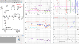
First off, ignore that bass hump. Its not accurate but the rest of this is.
My plan is to use all high quality components in my newest crossover simply because the XO will be mounted on the wall of my office and will be visible to anyone. I was going to use all air core inductors, however, the DCR of the large inductors is takes away a full 1.8db of sensitivity from the entire build. I wouldn't have to pad the mid of the tweeter as much since I could bring those up to match.
This is already a pretty hard to drive speaker. If it weren't for the ribbon I'd be considering active even though I know very little about active outside of the DSP of the head unit of my car which is far and away from hifi. Basically the definition of lofi.
The XO on the woofer is pretty high so I wanted to use air core here but do you think that is really worth it at the expense of sensitivity?
Attachments

Hi!
This subject has many different opinions, some like iron core others no.
In my designs, I use iron core for the woofer since I like to cut between 300 to 500Hz, so the inductor is always somehow big for air core (>3mH).
If you design correctly, with good margin to the saturation, it's ok to use iron core.
I had a post sometime ago, with the calculations and actual results, where I discussed this issue here and got help to solve a specific problem I've got at that time.
I test the inductor maximum current by applying a repetitive step fixed voltage. See scope pictures.
I also use this procedure to double check the inductance using the formula V=L*(di/dt)
I limit the iron core "gain", using an air gap, to a maximum of 10 to 15 times, so as to keep some minimum linearity.
So for a 4mH inductor, you can build a 250uH to 400uH and adjust through the gap to achieve 4mH
Less gain, more linearity, more distant from the saturation. More gain, less linearity and closer to the saturation.
This subject has many different opinions, some like iron core others no.
In my designs, I use iron core for the woofer since I like to cut between 300 to 500Hz, so the inductor is always somehow big for air core (>3mH).
If you design correctly, with good margin to the saturation, it's ok to use iron core.
I had a post sometime ago, with the calculations and actual results, where I discussed this issue here and got help to solve a specific problem I've got at that time.
Ferrite E-cores with gaps have the gap in the centre pole which keeps it away from any nearby metal. And since they use two E cores together you can have single or double gap by using one or two gapped pieces in the stack.
I test the inductor maximum current by applying a repetitive step fixed voltage. See scope pictures.
I also use this procedure to double check the inductance using the formula V=L*(di/dt)
I limit the iron core "gain", using an air gap, to a maximum of 10 to 15 times, so as to keep some minimum linearity.
So for a 4mH inductor, you can build a 250uH to 400uH and adjust through the gap to achieve 4mH
Less gain, more linearity, more distant from the saturation. More gain, less linearity and closer to the saturation.
Last edited:

You need thick wire for low DCR of the air core.
3.33mH 14AWG Perfect Layer Solen inductor at Madisound is $51.80 - BUT it gives you DCR of 0.45 ohms.
2.50 mH is $46.10 with a DCR of .36 ohms.
All about tradeoffs - $200 of air core inductors to keep that DCR down (and look cool).
(They also have 15 AWG for less, but higher DCR)
I like the sleek look of the laminate core inductors at JF components.
The cheap Dutchman inside of me screams at this. I feel like I could 3d print a winder and use a little motor I have laying around to wind my own air core inductors. Just pay for the copper.$200 of air core inductors
Honestly a little more concerned with your impedance and transfer function charts. This seems like a hard set of drivers to match up.
One other thing to consider is that the DCR is sometimes helpful in the baffle step compensation, so make sure you have taken that into consideration before you order any parts.
One other thing to consider is that the DCR is sometimes helpful in the baffle step compensation, so make sure you have taken that into consideration before you order any parts.
The cheap Dutchman inside of me screams at this. I feel like I could 3d print a winder and use a little motor I have laying around to wind my own air core inductors. Just pay for the copper.
Yeah, I wasn't recommending it, just making sure you knew it was an option.
Oh yes, yes it is. This is an exercise in difficulty. These drivers are incredibly hard to use and to pair and will be incredibly hard to drive.Honestly a little more concerned with your impedance and transfer function charts. This seems like a hard set of drivers to match up.
However, I will be using it at very low volumes inside of my office only within a 0-10 degree window. So I'm getting away with it.
Theoretically, this should have more detail than anything else I have made. We are talking about 0.2% distortion max across the entire range of 100hz-35khz according to my low volume level measurements. Ehile still getting down to and F3 of 37 Hz.
Baffle step isn't a big issue here. Because the enclosure is a series of teardrop shapes combined. I modeled it in vituixcad anyways and applied it to the sim though it doesn't seem to really change anything because the shape is so effective.One other thing to consider is that the DCR is sometimes helpful in the baffle step compensation, so make sure you have taken that into consideration before you order any parts.
You need thick wire for low DCR of the air core.
3.33mH 14AWG Perfect Layer Solen inductor at Madisound is $51.80 - BUT it gives you DCR of 0.45 ohms.
2.50 mH is $46.10 with a DCR of .36 ohms.
All about tradeoffs - $200 of air core inductors to keep that DCR down (and look cool).
(They also have 15 AWG for less, but higher DCR)
I like the sleek look of the laminate core inductors at JF components.
For lowest dcr but higher inductance coils use this: https://uscoils.us/product/ussq55-12-3300/
I see the inductor in that last link is out of stock and "Available on backorder." You can use a plastic rod or pill bottle or 3d-print your own form and wind your own. Here's a source for wire (I've ordered from here several times, everything I've ordered has always been in stock), you can decide your own tradeoff between coil resistance and AWG:
https://www.remingtonindustries.com/magnet-wire/
https://www.remingtonindustries.com/magnet-wire/
I been there , done that, maybe for small coils, the DIY will work, but NOT larger value coils with thicker wire,
and you really have to take in consideration the material cost, https://www.remingtonindustries.com/magnet-wire/magnet-wire-14-awg-enameled-copper-8-spool-sizes/ the price for 2.5 pounds copper is 55.93$ and yet that https://uscoils.us/product/usav76-14-3300/ 3.3mH air coil 2.6 pounds coil cost $47.74
and you really have to take in consideration the material cost, https://www.remingtonindustries.com/magnet-wire/magnet-wire-14-awg-enameled-copper-8-spool-sizes/ the price for 2.5 pounds copper is 55.93$ and yet that https://uscoils.us/product/usav76-14-3300/ 3.3mH air coil 2.6 pounds coil cost $47.74
Yes, higher sensitivity with iron core is really worth it.The XO on the woofer is pretty high so I wanted to use air core here but do you think that is really worth it at the expense of sensitivity?
Crossover frequency for the woofer is not that high. Iron core inductors work well up to 3 kHz or so.
I think you overcomplicated the crossover - fourth order filters are rarely needed.
For accurate simulation, you must make measurements in full Spinorama - at least every 15 degrees.
I'll never understand why some of you always assume the person on the other side of the screen doesn't know what they are doing. Is it a self sense of superiority? Is a lack of ego that you try to fill here? Not sure...I think you overcomplicated the crossover - fourth order filters are rarely needed.
For accurate simulation, you must make measurements in full Spinorama - at least every 15 degrees.
I took these measurements 4 times. I've been working on this for months. I have taken them in 5 degree increments though the window from 0-20 degrees is all that matters.
You have absolutely no idea. If I change any of those values or crossover point a fraction it upsets the entire balance. We are talking about a carbon woofer, a mid planar, and a ribbon tweeter with insanely erratic responses and they're off axis tk each other in both the vertical and horizontal planes. Everything in that network, is 100% necessary.
Then I would skip iron cores for indictors. They distort...My plan is to use all high quality components in my newest crossove
/
I'll never understand why anyone seeking an advice assumes the person on the other side (who is trying to help!) is trying to boost his ego?!I'll never understand why some of you always assume the person on the other side of the screen doesn't know what they are doing. Is it a self sense of superiority? Is a lack of ego that you try to fill here? Not sure...
No. Window from 0 to 180 degrees is all that matters (the full Spinorama). Measuring every 15 degrees is enough, but if you need a super precision - then every 10 degrees.I have taken them in 5 degree increments though the window from 0-20 degrees is all that matters.
From yours "the window from 0-20 degrees is all that matters", yes, I assume you don't know what you are doing. No hard feelings - I am trying to help you.
Of course any change in values will upset the entire balance. Instead of changing values (?) in the present crossover, I am suggesting you to try third-order filters instead of fourth-order.If I change any of those values or crossover point a fraction it upsets the entire balance.
I've seen conflicting data. I've seen measurement that show significantly higher distortion, especially 3rd order and I've seen where it showed very low distortion difference with a claim of no audible differenceThen I would skip iron cores for indictors. They distort...
Can I ask some questions without making you mad? What are you currently using for an frd? Is it a gated measurement with a tail added, or something else? Did you measure the zma, or use factory data?
My experience with Sims is that on my speakers, they are never accurate. There's several reasons though, and not necessarily the fault of the software. ( I cut corners.)
My experience with Sims is that on my speakers, they are never accurate. There's several reasons though, and not necessarily the fault of the software. ( I cut corners.)
OP said it will be teardrop shape, which is one of the best if not the best shapes acoustically. I played with round shapes and relatively narrow teardrop makes miracles. You can hear the difference, not just measure (!). The results of measurements will be good or very good because of the cabinet shape, but OP still has to make full 180 degrees at least in one direction. And that measurement has to be according to some standard - I use the way Mr. Kimmo Saunisto explained on his page to the letter. Also impedance measurements with drivers in the cabinets. After that the crossover will look different.
The bad part of unknown measurement type is that here we cannot see the whole picture. That red line on directivity graph should show meaningful and important data, but it does not. I can guess, that at the crossover point of tweeter here we can see some problem, but from 40 degrees of data it is hard to tell.
Imho, this speaker looks like something influenced by Mr. Troels or someone with unorthodox views: 27 parts on the crossover is so much Mr. Troels thing and those 2 parts OP is mentioning will have close to 0 effect on the sound quality with any choice. Yes, 4th order on woofer raises my eyebrow too. Mid driver looks like it behaves well with no wiggles seen on the drooping SPL curves on both sides, and probably can have more simple filter. Is mid too small and woofer too big? I have no idea...
This is like a secret date with female hyper-model: she is world-class, she is pretty, has carbon cheeks, some teardrop shaped body parts, will pose near office wall when asked, but everything else is a nightmare.
Maybe help from other members will be more directional if we knew the drivers used for the project? Partial or full photos of baffle?
Last edited:
My plan is to use all high quality components in my newest crossover simply because the XO will be mounted on the wall of my office and will be visible to anyone.
I'd focus first on improving the impedance from unnecessary dive. That 220uF could be improved. There is room
for achieving the same desirable FR without many parts. Midrange low pass inductors should
swap places and get adjusted.
Tweeter padding could be modified as well, series resistor belonging before filter and parallel part modded to match,
thereby preventing the 5 khz dive.
My plan is to use all high quality components in my newest crossover simply because the XO will be mounted on the wall of my office...
While considering cored inductors, try finding out under what circumstances would such one saturate.
Rarely do manufacturers mention any of this, and if so then insufficiently.
I did it once out of curiosity.
Post #6.
https://www.diyaudio.com/community/threads/saturated-low-pass-inductor.313449/#post-5212914
- Home
- Loudspeakers
- Multi-Way
- Air Core vs Iron Core - Sensitivity