It looks like the cabinet for the woofer will be about one cubic foot (30 litres) , sealed.
If the woofer is stated as 8", I'm assuming there will be another inch or so including the frame - there's no mounting information in the product description. So, 9" plus the distance from the edge of the woofer frame to the cabinet edge, say 2" each side for strength?
Therefore, let's say the cabinet needs to be around 13" wide, does that sound right?
Geoff
@GeoffMillar @Galu
The woofer is 10 inches!
The volume of the box will be 30 liters but I can increase it to 35 liters
The woofer is 10 inches!
The volume of the box will be 30 liters but I can increase it to 35 liters
Oops, my mistake!
When I searched for the Falcon XS 400 I came up with an 8" subwoofer.
Can you provide a link to the 10" version's specifications?
EDIT: Here they are: https://falconamplificadores.com.br/produtos/xs-400-10/
When I searched for the Falcon XS 400 I came up with an 8" subwoofer.
Can you provide a link to the 10" version's specifications?
EDIT: Here they are: https://falconamplificadores.com.br/produtos/xs-400-10/
The SPL of the Falcon XS 400 10" woofer is quoted as 87 dB/W/m.
I know you are aware that for a 3-way system the bass unit sensitivity needs to be higher than that of the mid driver, otherwise the mid driver will need to be attenuated.
What I am suggesting is that the degree of attenuation in dB required for the mid in your particular case would best be determined by experiment after you have built the system.
Actually, life would be so much easier if you were to use variable L pad controls on both tweeter and mid instead of fixed L pad resistors.
Here is an example from a UK supplier: https://willys-hifi.com/collections/l-pad-attenuators/products/4-ohm-l-pad-attenuator-50-watts
Do you have access to 4 ohm L pad controls in your location?
EDIT: The downside is the added expense!
Last edited:
I bought exactly these values of wire resistors1,5 Ω, 6,8 Ω, 0,47 Ω (ou 2 x 1,0Ω em paralelo) e 33 Ω.
I bought exactly these values of wire resistors
You are referring to your projected choice of L pad attenuating resistors: 1.5 Ω and 6.8 Ω for tweeter, plus 0.47 Ω and 33 Ω for mid driver.
It's been a while, so to recap:
Quoted woofer sensitivity = 87 dB/W/m
Estimated mid driver sensitivity = 89 dB/W/m
Quoted tweeter sensitivity = 91 dB/W/m
As indicated in post #35, Rs = 1.5 Ω and Rp = 6.8 Ω will attenuate the tweeter by around 4 dB and the mid driver may not require attenuation.
Have you actually BUILT anything yet?

Yes... I still need to finish the box.Have you actually BUILT anything yet?
I was just taking a look and reviewing everything on the website lol
I'll soon post a photo of everything ready and working
I'll soon post a photo of everything ready and working
I look forward to that eventuality!
I'll soon post a photo of everything ready and working
It appears, Pedroga, that your concept of "soon" differs radically from mine!

Still, it was worth the wait as you have done a good job of constructing the crossover board.
For ease of reference, I will append the crossover schematic (excluding resistors) below.
Dare I ask, how is the box construction coming along?
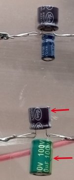
Er, it seems you have used polarised electrolytic capacitors.
I can see the negative polarity marker on at least two of them so I will assume the other two are also polarised.
This is a big mistake.
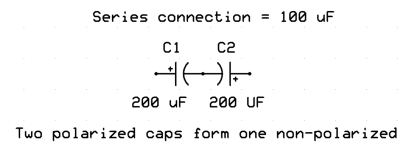
For a speaker crossover you Must always use non polar (NP) or bi polar (BP) capacitors.
Electrolytic type caps should have either NP or BP marked on them.
Or just use film caps and be done with it.
If Pedroga has used polarised electrolytic capacitors in his project then I'm afraid he hasn't paid sufficient attention to the 7 page discussion on crossover capacitors that he instigated in one of his previous threads: https://www.diyaudio.com/community/threads/crossover-the-infamous-capacitors.414191/
Calm down, calm down, guys from the forum, I paid attention to what you said about the capacitors.
I put these capacitors in temporarily for testing because I'm going to buy better quality capacitors.
As you said before, I should make a crossover where I could easily modify it "Constantly" and that's what I thought. I'M GOING TO CHANGE EVERYTHING.
In fact, it's working well, without many noise problems or anything like that.
Oh, I almost forgot, lol. I have a lot of work to do in my office, that's why it took me so long to post something here, guys.
@Galu @Lojzek @UserAbuser
- Home
- Loudspeakers
- Multi-Way
- Crossover! The construction

