Agree ….great, more 3D contours and actor showing more to floorHello rikiheck,
I have built my Wayne's BA2018 linestage with TOSHIBA TTC004B and TTA004B. Sounds great.
Cheers
Dirk
Last edited:

I've been wanting to try a Muse volume control for a while. Those look interesting. Not cheap, though.
The cost of a Gold Point 24 step Stepped Attenuator: $165 for stereo. Cost of an Academy Audio VCX+ with remote and power supply, $185 for the VCX+. The Goldpoints are certainly really nice. I have one on a headphone amp right now and it is very transparent. But the step size on it is 1.5dB. The step size on the Muses is 0.5dB so while this means more spins of the volume knob it also means you can probably find your favorite volume more easily.
This is a weird problem. Have built a number of matched transistor BA2018 boards (as described earlier in this thread) and they all sound splendid. One of them has developed a strange issue that is, kind of, an intermittent problem.
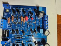
When this board is turned on, both channels work fine. Then, after about 20 minutes AND after a volume dip, the left channel (shown below) drops its output right at 6dB. It stays at this lower level for the rest of the listening session.
This happens every time.
Normal balance at first, then after 15-30 minutes (typically a record side e.g.) a drop of right around 6dB. Has happened so many times that I am sure of this description. Am using Goldpoint attenuators and can specify 6dB because the left channel knob has to be increased 4 steps to match the right channel after the weirdness sets in.
Can only speculate that some transistor (probably a SMD) fails after reaching operating temperature and is, oddly, only triggered off after a silence occurs in the line level content.
If anyone has had a similar problem, would appreciate your input. Am going to check all of the SMDs but think they are OK for continuity.
Attachments
Well what the ??? That's a crazy one, Craig. If the SMDs and transistors test fine then flip the board over and look for trouble with solder joints. If it were me, I'd just reheat most of them. Cold solder joints can do some weird things. The silence seems to be triggering an SMD or transistor to go low and stay low so this might be where to start.
Does this happen between tracks on a record? What if you listen to only the last track on a record? Plug some white noise into it and let it run for 45 minutes if you can. Finally, how long does it take for that channel to come back? Does a power down/restart work or is it an hour or so?
Does this happen between tracks on a record? What if you listen to only the last track on a record? Plug some white noise into it and let it run for 45 minutes if you can. Finally, how long does it take for that channel to come back? Does a power down/restart work or is it an hour or so?
At work we use a product made by Chemtronics called "Freez-It" to find thermal intermittent electrical components. For example if you're suspecting one of those SMD JFET's, you would wait until the board has gone into this failed mode, and then cool the component with the spray. Obviously paying attention to the system output level during this fault finding process.
Beyond that, possibly a bad solder joint somewhere? I would prefer to see a little better solder flow than what I'm seeing on that pcb. When you solder, feed in a little more than what you've been doing. Keep the iron there a little longer, for example, count to three. On something delicate, maybe closer to 2 seconds. SMD, even less than that. Don't move the iron during the 3 count, let the heat transfer do the work to create flow. A component ground plane solder connection needs even more patience and a little extra time. Don't be afraid to add a little flux to promote nice shiny smooth solder joints, just clean the board well afterwards. Equipment matters too. I typically use a 30 degree chisel tip on my PACE iron that's about the same width as the pad on the board, and have the temp in the 650-675 range for lead based solder.
Beyond that, possibly a bad solder joint somewhere? I would prefer to see a little better solder flow than what I'm seeing on that pcb. When you solder, feed in a little more than what you've been doing. Keep the iron there a little longer, for example, count to three. On something delicate, maybe closer to 2 seconds. SMD, even less than that. Don't move the iron during the 3 count, let the heat transfer do the work to create flow. A component ground plane solder connection needs even more patience and a little extra time. Don't be afraid to add a little flux to promote nice shiny smooth solder joints, just clean the board well afterwards. Equipment matters too. I typically use a 30 degree chisel tip on my PACE iron that's about the same width as the pad on the board, and have the temp in the 650-675 range for lead based solder.
@bhjazz and @william2001: Great ideas, guys. First, the problem stays on for the day and recurs immediately if the board is turned off for an hour or two. Only after it has sat all night does it act normal the following day for the first 20 minutes or so. It never happens during a listening period -- only after the line level has dropped and come back up -- again this always happens this way as strange as it sounds. Thought of the white noise idea but haven't had the time and the bipolar PSU together to try that yet.
Have not had any problems with cold solder joints in the many other boards made but that could, of course, be an issue. The solder side of the board looks very clean and I examined it again today.After you spray Freeze-it on a troubled part what does it do? Show some color? Or just return the volume level to its good state?
My temp gauge is at my other place along with most of my measuring equipment. Might be better to wait until May when I get back up north.
Thanks again you two.
… while I, as a [total] noob, would go after the attenuator, and switch channels to see how it behaves…
Have several spare ba2018s and when I switch them in the problem goes away. It's this particular pcb and channel.
4 channel digital scope + single shot triggering + a lot of patience. Have your USB thumb drive at the ready to grab a full resolution .PNG image of the screen. Have your phone's camera at the ready, as a backup, in case you fatfinger the screen capture or bump a knob you shouldna .
Buy one for every domicile where you might want to troubleshoot misbehaving audio gear. USD 699 , cheaper than a moving coil cartridge.
Good idea but I already did that and the used HP Agilent 54622D here in Phoenix has died due to connection problems. False economy has kept me from replacing it as I keep thinking the next fix will work.
BTW have been switching between premium (= matched transistors) and stock BA2018 builds and the audible difference is marked. Since I have become accustomed to the matched build, find it hard to listen to the stock sound ideal now. It's too harsh and brittle -- by a bunch.
BTW have been switching between premium (= matched transistors) and stock BA2018 builds and the audible difference is marked. Since I have become accustomed to the matched build, find it hard to listen to the stock sound ideal now. It's too harsh and brittle -- by a bunch.
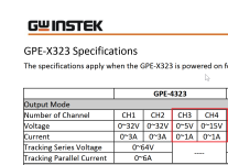
And BTW(2) has anyone found a Bench Power Supply that will output bipolar +/- PSU values for two PCB boards simultaneously? The only contender I can find is the Instek GPE-4323 4 channels unit available on Amazon -- but the quality looks suspect here.
Plenty of bench supplies have two independent outputs which you can configure with plugwires to provide +XX volts at YY milliamps, and also -JJ volts at KK milliamps. You get to choose the values of XX, YY, JJ, and KK --- four different numerical values. It's not required that XX=JJ nor is it required that YY=KK
I don't know of any which have four independent outputs with four user supplied voltages and four user supplied current limits.
I don't know of any which have four independent outputs with four user supplied voltages and four user supplied current limits.
This one does:
https://www.amazon.com/Instek-GPE-4...bdd43d&ref_=pd_hp_d_atf_ci_mcx_mr_ca_hp_atf_d
Have ordered one just to see if it will work. Dislike having to go through the plug-wire routine and want to be able to just select the values and plug them in.
https://www.amazon.com/Instek-GPE-4...bdd43d&ref_=pd_hp_d_atf_ci_mcx_mr_ca_hp_atf_d
Have ordered one just to see if it will work. Dislike having to go through the plug-wire routine and want to be able to just select the values and plug them in.
Have ordered one just to see if it will work.
Channels 3 and 4 look like fairly weak sisters to me, but if you're happy then: you're happy.
(link)
Attachments
Yep. Won't work after all. Wonder if any of the legacy PSUs on EBay will handle bipolar output for two boards.
Then, after about 20 minutes AND after a volume dip, the left channel (shown below) drops its output right at 6dB. It stays at this lower level for the rest of the listening session.
I think you describe a cold joint. Q22 source and Q21 gate on your photo look suspicious. Also solder not flown through many THT components increasing suspect field. R39 to GND and R27 to R40 for example. Like there are not enough flux or solder is lead free.
- Home
- Amplifiers
- Pass Labs
- Wayne's BA 2018 linestage