Many prefer to combine the HP xover slope with the mid driver low end rolloff slope. This saves xover components, providing a steeper filter slope. I prefer to cross above the natural HP slope of the mid enclosure, which gives me better control over the blended LF and MF response curve, avoiding the mid driver's resonance peak and providing better enclosure dampening combined with more cooling for the VC. Titanium formers don't transfer heat as well. The 18M4631T can deal with about 70W rms long term in a small sealed box but it will start compressing at 40W with about 1.5 dB output loss. 110+ dB peaks are no issue for this mid. Just watch the excursion carefully crossing it lower than 250 hz.

Can you please explain more about that, in a easy way to understand as a "non-expert" ?Many prefer to combine the HP xover slope with the mid driver low end rolloff slope. This saves xover components, providing a steeper filter slope. I prefer to cross above the natural HP slope of the mid enclosure, which gives me better control over the blended LF and MF response curve, avoiding the mid driver's resonance peak and providing better enclosure dampening combined with more cooling for the VC
Today (still final-tweaking) xo points are at ca 250 and 2550 hz, 12 dB ( SS18M, 18 dB at LP).
Using/testing different xovers on left and right speaker, and both sounds exelent!
1-1½ dB more output from right speakers xover, and little more "air" and "punsh" with compromise a litte lower impedance (still ca 3 ohm in 2-3 short dipps)
Speakers are today able to play´s "like a live consert drum solo" around "maximun output" with still inaudible distortion, but allmost no headroom left then so it something to always be concerned about.
And i know myself after a few (read 10-12) beer´s and hours of high level listening!
Is thinking about one more SS18M per side, In MTM?.
But my current design makes it difficult.
Regards John
Attachments
These drivers are some of the best cone mids I've heard at any price, especially in the lower mids. They have a pure, clean tone with excellent transient behavior. I've gotten the best sound from them with 6 dB HP filters at 250 hz crossed to a good 12" or dual 8 - 10" woofers. I dont like the sound of filters steeper than 1st order in the lower mids.
@profiguy:
I don’t own 18M, but I fully agree that in general 6 dB HP (electric) is a good starting point.
How would you rate 18M against other mids as:
Faital 6RS140
Vifa Neo
Or the like
Also on paper it looks like 18M might be happy with highish crossover like 2400 hz?
@yawen quote - "Can you please explain more about that, in a easy way to understand as a "non-expert" ?
For example, if your mid is in a small sealed box which rolls off 150 hz @ the typical 12dB/octave of a sealed box, you simply add a 2nd order HP crossover at 150 hz. This combines as an acoustical 4th order slope at 150 hz, resulting in a 4th order slope for the cost of only a 2nd order electrical filter. It also improves acoustic power handling if the woofer can deal with the electrical power handling of the relatively low crossover. That driver will be happy at that HP point in a system with a total of 200W power handling. Thats due to how the percentages of power divide out with typical spectral distribution of power in music.
With pink noise at 150 hz crossover, the LF would see roughly 40 percent of the total system power handling capacity. With modern, densely mixed music it would be more like roughly 60 percent. The 50/50 point with pink noise would be between 300 - 400 hz, but thats more like classical music.
Thanks for explaining !if your mid is in a small sealed box
I was thinking is was around that, but doesen´t get it all yet.
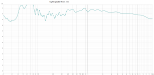
For exemple, this is a 1 meter measure, box is 4 liter closed (heavily dampened) without xover.
Where should i consider the natural roll-of?
At 120 hz or at 280 hz?
regards John
Attachments

@jawen What does your impedance curve look like in that 4 ltr box and is that the actual FR curve you just posted? It appears to be measured too low in level or too far away from the mic.
It will depend on the midrange sensitivity you need to get linear FR in conjunction with the woofer you're using. Power handling will also dictate the crossover point. With baffle step you get another 6dB/oct slope upwards so you'll need to factor that as well.
In 9 to 12 ltrs you'll see a 150 hz F3. Thats too low for power handling if you want it to play very loud and hold up in a 110 dB peak SPL system. I'd recommend at least 5 Ltrs which will give you a slight SPL bump from the higher Qtc. You'll need to sim this to be sure, but I'd recommend a 300 hz 2nd order HP and ditch the lower xover idea. The electrical power handling won't be sufficient with a HP lower than 200 hz and you'll be close on the xmax there as well. You can reduce the enclosure size but that will hurt thermal power handling. You'll also be in the impedance peak range with your HP which will cause linearity and phase issies.
I've used the 18M4631T in 10 ltrs sealed with a 250 hz 2nd order HP. This was in a 3 way along with a SB34NRXL 12" LF and T35C002 Seas tweeter in a WG crossed at 2.6k. 110 dB peaks were no issue at all and the mids were very clean, natural and accurate. The baffle was large on these speakers which made the crossover easy with very little BSC on the mid.
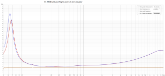
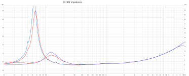
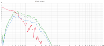
Here is both SS18M in air free and in the 4 lit boxes.What does your impedance curve look like in that 4 ltr box
My impedance-gigg has disturbances at 50, 100, 150 hz, so ignore that.
Here is with prototype-baffle under the small SS18M cabinette (39 cm wide and 63 cm high)and is that the actual FR curve you just posted? It appears to be measured too low in level or too far away from the mic.
My plan design was having 15 inch Dayton 390ho playing sideways, but today i have it facing forward, so baffle under the SS18M cabinette is 56 cm wide and 63 cm high.
Think measurement are from 1 m but im not sure.
And the level is not 2,83 V/ 1W
Attachments

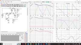
Todays xover.but I'd recommend a 300 hz 2nd order HP
Attachments
I am guessing that as you try to move towards 300Hz for the mid, managing the blend with the Eminence bass is tricky.
In that if you lessen the bass driver roll of to the mid it may sound too thick with some voices?
I can see the data for your current 200Hz or so crossing point achieved today how does it sound in comparison to where your were earlier, as you have been working on this for a while you obviously know how difficult it is to get that voice balance right.
Hi there Ray 🙂how does it sound in comparison to where your were earlier,
In this passive xover-build, Vitauxcad "somehow" showed small peaks from both the SS9300 and SS18M, which turned out not to be present in the "real" measurements later. (measurement are real hard to do even 80% correctly)
So this time i had to use Vitauxcad even "more" like a starting point, and do most of the xover-building/testing during all measurements.
I also started with woofer playing sideway´s, and that was giving me "less" possibilities regarding crossover frequency.
1 week ago i turned the woofer so it plays forward the listener
.And that gives a much bigger baffle for the midrange "to work with", and also more "hump" from the 15 inch woofer.
And also "bigger" possibilities regarding crossover frequency to the mid.
But i feel im near nirvana now, because now i want to listening higher and higher (good sign for me, because my ears and head can´t stand specific distortion at all, or a "to sharp" tweeter)
The SS18M is really really good compered to "all" midranges, even if a few midranges have a little more "details clearer".
Over-all this midrange have very few "compromises", IF you also want to be able to play real high spl.
Always hard to describe sound, but feel it´s more "live-like" punch and "air" to the music now.
Paper-cones have a certain sound from them, which is very pleasant and that feel "real"
Will work a little more on "woofer to midrange" overlap, and make more woofer measurements.
regards John
@jawen:
Thanks for sharing your impressions.
I highly encourage you to build turntable so you can make proper off axis measurements.
https://kimmosaunisto.net/Software/VituixCAD/VituixCAD_Measurement_REW.pdf
Learning curve is steep, but IMO worth the effort.
One quick tip is you haven’t set distance from center of tweeter to center mid and woofer (Y parameter in millimeter)
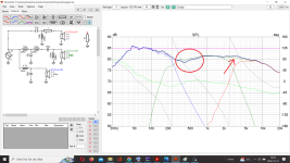
When i put the Y parameters (340 mm woofer to mid, and 175 mm mid to tweeter)One quick tip is you haven’t set distance from center of tweeter to center mid and woofer (Y parameter in millimeter
I get this in Vitauxcad.
Something called "listening window (red arrow)
But someting going on in the area in red circle?
And measured responce is better then Vituaxcad shows 👍
Attachments

Y values should be minus ( ex -340) because mid and bass is below tweeter.
Exactly what is going on is difficult to know. I don’t know how to make a passive filter.
In order to do it right you must merge near- and farfield and combine with diffraction/baffle simulation.
In order to make sanity check, you can try take near field measurement at exactly center between mid and bass at a distance at 5 mm from baffle. Then some around that. Those should look similar to curve in VCad in bass/low mid.
@jawen You have a phase issue from LF to MF causing a dip on axis. The LF will lag behind the MF at crossover, so you want both to sum with the same difference in phase lag. You should see up to 3 dB bump along the crossover point with BW filter slopes and 0 dB with LR filter slopes if both phase relation trends are equal ie. sum properly. Sometimes you can get away with mixed slopes with an additional 6 dB/oct slope on the MF to pull non-aligned VC planes into a better phase relationship. I use mixed slopes on many 2 way setups for tweeters that sit flush in the baffle with larger woofers (deep cone placing VC further behind the tweeter VC).
Profiguy has pointed out the issue of phase matching between LF and HF and how ideally they should sum in different ways for Butterworth and Linkwitz-Riley filters. Unfortunately you are left with trying to balance these design aims against keeping away from a minimum of three ohm impedance with reasonable phase in the 200-500Hz area. As far as i can judge your acoustic slopes are at basically third order, with electrical slopes second order ish looking at the data.
If you are enjoying the sound you are getting now make sure you have saved the crossover config, so that you can get back to it again.
In VituixCad in the lower part of the crossover window your filter is annotated as Variant S1 highlighted in red.
Its the column just above your Mozilla Firefox icon on your desktop.
Now click in Window S2. If I have this right it should have just duplicated your original filter into the S2 Area.
Assuming you have had breakfast and a good coffee, put some favourite music on and play around with components in the S2 filter area and see what you can come up with. When you get bored or have to do some chores hit save, and come back to it later. Enjoy. 🙂
Not knowing how this will work, maybe swap the phase of the midrange and look at the resulting mess or beautiful suck out you now have between the Bass and midrange. you could try lessening the roll of of the bass driver and see if you can obtain a nicer more symmetrical suck out. After a few small component value changes, swap the midrange phase back to see how that has affected the response. Little steps on either channel and compromise i think is the name of the game here.
If you can achieve a nice transition here, you may have to go back to the mid tweeter responses and adjust them work with the new balance.
You can also compare the original S1 and S2, simply by selecting the relevant Non Red box, i.e. the blue R1 and R2. In my mind I equate S=Save and R = Review.
I had not know what these S1, S2 etc was, but because it has R1 etc after i thought i was about resistors or something hahaha.In VituixCad in the lower part of the crossover window your filter is annotated as Variant S1 highlighted in red.
Its the column just above your Mozilla Firefox icon on your desktop.
Now click in Window S2. If I have this right it should have just duplicated your original filter into the S2 Area.
Will try to make som woofer measurements today, and go from there.
Just to learn, can you show me how you see that pleasev 👍the issue of phase matching between LF and HF
regards John
Do you see that because the behavior att crossing LF to MF ?You have a phase issue from LF to MF causing a dip on axis.
My red ring in the picture?
Attachments
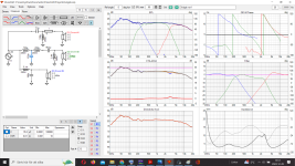
Yes, that's a bit better in my eyes.
You have smoothed the transition a bit more and your crossover has moved to around 275Hz. In your previous post where you had drawn the red circle if you redraw it over the 275 Hz point you have a very small dip. I wouldnt fret about it as a small dip.
But as you have progressed, some more today can you change it and lessen the dip. I ask as it maybe one or two more component change away, or it simply cannot be improved easily by a electrical filter change.
Probably moving the mid enclosure a small bit either backwards or forwards would have a bigger effect.
Which again you can try in VituixCad as Roky, pointed out by changing the position of the mid enclosure by adjusting the Z value I think. I would need to read the help file to understand if + corresponds to forward or Moving the enclosure away from the listener. I don't have the software on my laptop so cannot easily look at the help file.
- Home
- Loudspeakers
- Multi-Way
- Maximize a Scanspeak 18M/4631 T00 Revelator midrange for a 3 way