...if the amp is prone.
Exactly. "If the amp is prone" to infrasonic oscillation already, choosing a lower value than usual Ck is a band-aid fix. That low value of Ck can also cause a bass boost from the higher Q resonance slightly higher in frequency from the F3 'zero' -- especially if a frequency limited device like an audio transformer is the plate load for that circuit.
My thought is that the better solution would be to find out why the circuit is prone to instability at low frequencies in the first place, and fix that problem. Then choose Ck for best audio performance (whatever the designer of the circuit might think that should be).
Or leave Ck off completely, if you can (although with a transformer load this will raise the triode's rp and can cause a noticeable lack of bass response due to limited primary inductance of the transformer).
Thanks. That's what I thought I'd found in testing, but I was beginning to doubt my thinking.
Can you think of an example of a triode with 1/gm >> Rk?
You could always bias a triode at some very small negative grid voltage and then lower the anode voltage to get the anode current that you want, but you will get some grid current then. An ECC83 is still supposed to have negligible grid current at -0.9 V grid voltage, so maybe an ECC83 with -0.9 V grid voltage, 250 V anode voltage and 3.3 mA anode current? Rk would be about 270 ohm and 1/gm would be about 400 ohm, according to this datasheet: http://www.r-type.org/pdfs/ecc83.pdf 1 + gmRk is then approximately 1.68.
If I take type 5687 and really roast it with Ea = 120V, Ia = 36mA, Ec = -2V, I get
1/gm = 1/11.5 mA/V = 87
Rk = 55.55 ohms
Does that qualify as 1/gm >> Rk?
It's better than my example, but you are still off by a factor of about 1.64 when you neglect the series feedback.
If I understand it correctly, you'd see that only running relatively high gm triodes at low voltages and high plate currents (for lowest impedance).
Not necessarily, see my ECC83 example.

Thanks. I have a lot to learn... Like how to calculate the amount of degenerative (series?) feedback from an unbypassed Rk. I have a copy of the RDH4. I have some bedtime reading to do.
I should rethink my statement. Maybe this works in its place:
You'll see that only by running a triode with as high plate current as you can get away with, to goose its gm. However, this risks bringing on grid current in many triodes.
I should rethink my statement. Maybe this works in its place:
You'll see that only by running a triode with as high plate current as you can get away with, to goose its gm. However, this risks bringing on grid current in many triodes.
A good approximation for degeneration is to imagine the cathode's 1/Gm as a "real" resistor, then add the external cathode bias resistor in series. Then the composite sum acts as if it were the "real" 1/Gm.
Bypass capacitors cannot be counted on to provide a pole because the zero is usually so close in frequency. Best to try to brute-force design them out.
All good fortune,
Chris
Bypass capacitors cannot be counted on to provide a pole because the zero is usually so close in frequency. Best to try to brute-force design them out.
All good fortune,
Chris
Last edited:
Quite true.
That's one reason for the popularity of putting an LED in the cathode to bias the tube. You get the voltage drop across the LED to put the tube's cathode above ground, making the grid negative. The LED internal resistance stays pretty constant across a wider than audio frequency range and at pretty much all signal levels.
I tried that with my headphone amp, but I had to parallel three green LEDs to get grid bias of -2V while not exceeding the 20mA max rating of the LED, because the tube is biased to draw 40mA plate current. It worked but I found I preferred the sound I got using a fully bypassed cathode load resistor. It could be that I have bad taste. Maybe I was using 'bad sounding' LEDs. I don't know. However, I never play headphones loud enough to get anywhere near clipping, so the bias drift issue doesn't seem to matter.
For simple gain stages I'll usually use an unbypassed Rk and design around the higher rp and lower gain. So I guess I agree with you! 🙂
Wow, thanks for all the great feedback.
I should point out the following.
This circuit has been in use in my 211 amplifier for 30 years, and I am in the process of updating things for improvements, based upon what I know about component choices, for sound quality not the circuit design!
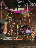
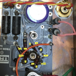
30 years ago I designed the layout of a 211 amplifier using the infamous Ongaku design and tried to build this myself, however I ran out of time and talent (got confused with the power supply) and so I had a friend complete it in the end. However he changed the design completely to one of his own (he makes small volume tube amplifiers) and this is what I got back. It's not really what I had intended but I was told this would be more suitable for my 104dB speakers I was using at the time. He never gave me a circuit diagram and refuses to tell me :-( he is very secretive about his designs! He even covered up the LL1660 and I had to work this out with measurements, appearance and layout 🙂 It's here and it's circuit Alt.S on the 2nd page.
The circuit is how I understood it looking at the actual connections in the amplifier itself, the power supply and Lundahl interstage seem to connect to the circuit in the way shown. The PC645 of course has 4 cathodes and the way they are connected is with 25R on each one and then 100R in series across all 4 hence the diagram.
The heater is AC supplied.
Best case scenario is I can get away with a 200uF or even 100uF cathode bypass capacitor as I have some (100uF) that sound fabulous every time i use them, and they are not expensive.
My horn speakers actually roll of at 58Hz and so I have two subwoofers that I run to fill the gap to 15Hz or so and this would allow me to not care so much if it was slightly rolled off as this would be easily remedied. I am also sure most of you are familiar with measuring in room response in a real room with real speakers that the frequency response is anything but flat at the bottom 50Hz!!
I just want to know what the reality of the change from 1000uF to 100 or 200uF would likely mean, the obvious answer might be, hey just measure it! but as the amplifier is 50Kg+ on a re-enforced wall shelf and kind of hard to move and handle alone I always have to ask a friend around to help and it's not a simple convenient task!
Thanks, again and Merry Christmas!
Rich
I should point out the following.
This circuit has been in use in my 211 amplifier for 30 years, and I am in the process of updating things for improvements, based upon what I know about component choices, for sound quality not the circuit design!
30 years ago I designed the layout of a 211 amplifier using the infamous Ongaku design and tried to build this myself, however I ran out of time and talent (got confused with the power supply) and so I had a friend complete it in the end. However he changed the design completely to one of his own (he makes small volume tube amplifiers) and this is what I got back. It's not really what I had intended but I was told this would be more suitable for my 104dB speakers I was using at the time. He never gave me a circuit diagram and refuses to tell me :-( he is very secretive about his designs! He even covered up the LL1660 and I had to work this out with measurements, appearance and layout 🙂 It's here and it's circuit Alt.S on the 2nd page.
The circuit is how I understood it looking at the actual connections in the amplifier itself, the power supply and Lundahl interstage seem to connect to the circuit in the way shown. The PC645 of course has 4 cathodes and the way they are connected is with 25R on each one and then 100R in series across all 4 hence the diagram.
The heater is AC supplied.
Best case scenario is I can get away with a 200uF or even 100uF cathode bypass capacitor as I have some (100uF) that sound fabulous every time i use them, and they are not expensive.
My horn speakers actually roll of at 58Hz and so I have two subwoofers that I run to fill the gap to 15Hz or so and this would allow me to not care so much if it was slightly rolled off as this would be easily remedied. I am also sure most of you are familiar with measuring in room response in a real room with real speakers that the frequency response is anything but flat at the bottom 50Hz!!
I just want to know what the reality of the change from 1000uF to 100 or 200uF would likely mean, the obvious answer might be, hey just measure it! but as the amplifier is 50Kg+ on a re-enforced wall shelf and kind of hard to move and handle alone I always have to ask a friend around to help and it's not a simple convenient task!
Thanks, again and Merry Christmas!
Rich
Attachments
Hi Rich
You could probably also try using a cheap red LED instead of the RC network on the cathode. That's another option.
But since you are rolling off anyway around 50Hz, the 100uF bypass cap might be fine as well. Your sub-woofers are not connected to this amp - right?
I see now that you don't have a diagram of the power supply. I am pretty sure the B+ on the 6C45pi is not the same as for the 811. Also, the 6c45pi has one cathode (pin 9).
Btw - if your friend doesn't share the circuit diagram for your amp with you, I wouldn't say he's much of a friend... But I suppose you know that.
The right one would be 159155: it is simply 1/2pi if you consider resistor in Ohm and capacitor in uF.I've found that a shortcut for finding the value of Ck for f = 1Hz is 156,000/Rk.
You can round it to 160000.
The subs are coming off the 211 on a high level input (sounds better than from the preamp)
Also just a question why is everyone focused on a roll off at f= 1Hz, not say 20Hz?
Also just a question why is everyone focused on a roll off at f= 1Hz, not say 20Hz?
I said that because it is far too specific a number to be usable as a general rule. It can’t possibly apply to all valves and all reasonable values of Rl.Can you give some more detail on why you say that?
The RDH does give a general rule, that Z(C) should be > 10 times Rk at all frequencies of interest.
interestingly and confusingly the interstage transformer itself has frequency response, that seems to roll of at 25Hz in any case!!
If you believe that you can hear the effect of the cathode bypass capacitor, then you would want to minimize its effect. The more signal voltage across that capacitor, the greater its effect, and the smaller the value of it the greater the signal voltage across it, so the greater the effect.why is everyone focused on a roll off at f= 1Hz, not say 20Hz?
Your "friend" seems to believe that there are secret sauce magic formulas about near century old technology. The secret sauce is half and half catsup and mayonnaise from Sysco. A real Ongaku isn't hard to make, except for the 16kOhm OPTs (originals had silver windings). Dave Slagle could make up a pair, but they'd be expensive.
There is no Sanity Clause, but Rudolf is alive and well,
All good fortune,
Chris
Oops, that should be < Rk/10, of course.The RDH does give a general rule, that Z(C) should be > 10 times Rk at all frequencies of interest.
Sorry, I should have said that B+ for the 6c45 results in 139V at the valve anode, it is like this before feeding the transformer when I measured things and tried to make sense of the Power supply.For 100 ohms, the bias is not going to be very much so yes, your bypass cap could very well be un-necessary. The formula that has been noted is from the Radiotron Designer's Handbook, 4th edition, (Harrison: RCA, 1953), page 484. - F. Langford-Smith, editor.
I think rongon's math is not far off. "For 100R, Ck = 1500uF gives you F3 of about 1Hz." I calculated 1600uF for 1Hz. - do you listen to vinyl records? maybe you won't want such a low cut-off to hear the rumble of the record player...
For 20Hz, go for around 100uF. The precise value was 76.8uF
Also - I see '4x 25 ohm' allen bradley for the cathode resistor on your schematic. Just get a decent 100 ohm metal film. Btw - there is usually no problem finding 120 ohm metal film resistors if you want... Also, If you want, user higher valued resistors in parallel to trim to a precise value. I always find this to be much easier than resistors in series...
Ok.. here is the tough part: I hate to say this, but your schematic looks faulty to me. Maybe I am wrong. I hope so. Prove me wrong please. 🙂
The LL1660 has a source impedance of only 14k ohm. If you are trying to drop 860 volts across it's primary while drawing 13-16mA then Ohm's law tells me that won't work. I am assuming here you were wanting to do SE to SE Interstage 4 : 4.5 with this LL1660 right? I am pulling this 14k ohm primary impedance value straight off the Lundahl specs sheet.
Ohm's law tells me that your 6C45pi plate is going to be at 1000v-200v = 800V if this is the case... Is this what you wanted? or is your B+ on the 6C45pi something different than 1000v? Sorry for asking these painful questions. The other posters probably think the same thing but are hesitant to stick their fingers in the socket. Tell me that the value for the 6C45pi is a different B++ value than the B+ for the 211 and it is significantly lower than 1000v... 😉
Also those russian valves (tubes) are cheap for a reason (sorry to say). The 6C45pi sounds really good but you need to carefully measure and select them using a (digitally) calibrated valve (tube) tester to find ones that match the specs sheet (or for whatever purpose you want them for). They are supposed to have an amplification factor of 52, but I found most of them to be +/- 10% (sometimes more). Maybe 1/10 fit the specs sheet numbers. Of course you could buy a LOT of them and test them... Just warning you. I got a whole box of them years ago for less than $5 apiece. Now they want something rediculous like $40 apiece for them. The world is insane today....
That said, they are super nice sounding and rugged tubes. But clearly they were hard to build to a narrow standard. I ONLY use them with SS regulation. Then they sound FANTASTIC If (and only If) you can dial in the correct operating point and bias easily. That is hard to do with a plate choke vs. SS regulation.
You can consider looking for some other plate choke with much higher primary inductance... I think you will find that its hard to find an ideal one. Maybe you can wind your own (some DIY'ers do this). Eventually you might land on the idea to use a separate plate choke and inter-stage choke. Been there, done that. It gets HEAVY and needs additional space plus it costs a lot more than originally budgeted for...
Anyway, please advise us on this schematic - it seems to be missing some information for me at least.
Yeah its wired as Alt.S 4:4.5
I would still love to know how to calculate the " Total effective plate load resistance, k ohms" of the interstage to complete this calculation here
I understand that the transformer has inductance and so this acts as an impedance load in the same way as a resistor, but be great to understand the maths to plug in to this calculator, assuming this would provide a theoretically correct answer.
Thanks!
For the record, the way I usually calculate the required cathode bypass capacitance is a bit too conservative. I usually do what I wrote here: https://www.diyaudio.com/community/...-cathode-bypass-capacitor.396622/post-7288119
I neglected the internal resistance of the valve, but the current division between the load and the internal resistance has approximately the same effect as a lower transconductance. That is, when you calculate gmd = gm ri/(ri + RL) and fill in that in the equation for the cut-off frequency, you get closer to the truth than when you fill in the full gm.
ri is supposed to be the internal resistance and RL the load resistance (typically the parallel value of the anode resistor's resistance and the input impedance of the next stage).
I understand that the transformer has inductance and so this acts as an impedance load in the same way as a resistor, but be great to understand the maths to plug in to this calculator
The difference between a plate load resistor and a plate transformer is that the resistor's impedance is not frequency dependent (it's got the same value of ohms at all frequencies of interest) while a transformer is bandwidth limited by its primary inductance (defines low frequency limit) and parasitic capacitance and leakage inductance (defines high frequency limit and resonant behaviors).
Did you post how you have the LL1660 transformer wired up? What is its primary inductance?
https://jacmusic.com/lundahl/datasheets/1660s.pdf
Looking at the data sheet, it looks like the LL1660 is meant for use as
1) a single-ended to push-pull interstage transformer with 42H primary inductance, or
2) a push-pull to push-pull interstage transformer with 240H primary inductance.
I don't see specs for use as a single-ended to single-ended interstage transformer.
Once again, we don't have enough data to be able to make recommendations with any certainty.
This is great learning thanks!
The pdf for L1660 is here, that one is for L1660S Single ended to single ended in my application is Alt.S and inductance is 130H.
Would this make the impedance 2 x Pi x f x L (say at 20HZ) = 16K ?
Rich
Perhaps the best way to resolve this on reflection is to experiment and use the real test method!
I will take a sweep across the 211 in situ and see how this performs using REW as it's easy to manage, under 2V output with REW software and a usb DAC.
I can leave the speakers connected (recognising this is an uneven impedance load, but also this is real life) I can then keep this and do the same with the modified circuit using say 200uF on a first trial, and then see if I need to add more to get some LF response back (or not!) compared to the current sweep.
I will post the existing sweep here when I do this next year, and then try a 200uF
Rich
I think you can analyse it in terms of a damped LC network. According to a calculation I just did, the impedance looking into the cathode of a valve with transconductance gm and internal resistance ri loaded by an inductance L is the series connection of an inductance
L/(rigm + 1)
and a resistance
ri/(rigm + 1) ~= 1/gm when rigm >> 1
Of course, rigm is simply the voltage gain mu of the valve.
This impedance in parallel with the impedances of the cathode resistor and cathode decoupling capacitor has the same poles as the transfer from grid voltage to voltage across the inductive load. That transfer has two zeros, one at 0 and one at the place Merlin indicated early in this thread.
- Home
- Amplifiers
- Tubes / Valves
- Cathode bypass calculator help