On the subject of q.s. you should check this DAC out, a very nice unit that responds well to improvements in output capacitors and power supply.
It lacks the 'digital' sound footprint of higher resolution units and this makes it sound much better in the opinion of myself and friends.
https://www.aliexpress.com/item/100....order_list.order_list_main.28.375f1802BH1boU
Haver a magical and successful 2025

It lacks the 'digital' sound footprint of higher resolution units and this makes it sound much better in the opinion of myself and friends.
https://www.aliexpress.com/item/100....order_list.order_list_main.28.375f1802BH1boU
Haver a magical and successful 2025
If you are into valves and DACs:
I doubt if it meets the q.s. requirement, though.
Happy 2025!
I doubt if it meets the q.s. requirement, though.
Happy 2025!
From my website:
Now let us look at the capacitor, Ck, this capacitor not only sees the cathode resistor, but also the anode resistor and the valve resistance, Ri, in series, remember the HT is ac ground through the capacitors in the power supply. The value of these resistors are also influenced by the gain of the valve itself, so the resulting resistance, rk, must be calculated as:

However, the capacitor off course also sees the cathode resistor in parallel with rk, so:

And, finally the capacitor Ck:

Where fn is the lowest amplified frequency, -3 dB point.
Something like this:

For more info see my website:
https://tubes.njunis.net/?p=518&lang=en
Now let us look at the capacitor, Ck, this capacitor not only sees the cathode resistor, but also the anode resistor and the valve resistance, Ri, in series, remember the HT is ac ground through the capacitors in the power supply. The value of these resistors are also influenced by the gain of the valve itself, so the resulting resistance, rk, must be calculated as:
However, the capacitor off course also sees the cathode resistor in parallel with rk, so:
And, finally the capacitor Ck:
Where fn is the lowest amplified frequency, -3 dB point.
Something like this:
For more info see my website:
https://tubes.njunis.net/?p=518&lang=en
Spot on, but in this case Ra is an inductor (the primary of an interstage transformer).

It's a transformer with no resistive load.
My solution is attached to post #47, by the way. It boils down to transforming the inductive load impedance to the cathode in much the same way as you do for Ra, and then calculating the natural frequency and quality factor for the damped LC tank that you get. At least that's for the poles, the zeros follow by inspection of the original circuit.
My solution is attached to post #47, by the way. It boils down to transforming the inductive load impedance to the cathode in much the same way as you do for Ra, and then calculating the natural frequency and quality factor for the damped LC tank that you get. At least that's for the poles, the zeros follow by inspection of the original circuit.
Last edited:
The tube internal resistance and the plate load resistor will be in parallel with the Kr, because of the bypass cap point in the circuit. Think of it this way, if the K was grounded as in a fixed bias config. the Kr is 0 ohms no matter what the other loads are. Not series. So that makes the Kr just a bit smaller. So you can toss the other load factors and just use Kr and C for the rolloff point calculation. It's a horseshoe calculation. Don't make this issue more complex that it has to be.
Ditto. When you put 100K in parallel with 2K, it ain't worth the effort to hit the calculator buttons.
As an example without any transformers, if you have a triode from an ECC83 with mu = 100 with a 1.8 kohm cathode resistor, 75 kohm connected to the anode (anode resistor in parallel with the input impedance of the next stage) and 75 kohm internal resistance, the resistance looking into the cathode is (75 kohm + 75 kohm)/(100 + 1) ~= 1485 ohm. That comes in parallel with the 1800 ohm cathode resistor, so when you neglect it, you are off by more than a factor of two.
It's basically this. When you look at the admittance at the cathode without the cathode resistor Rk and the cathode decoupling, you get a term that comes from ri in series with L (or RA or whatever is connected to the anode) being connected between the cathode (node K) and AC ground (node 0), but there is also the current through the controlled source that gets divided between ri and L. That current turns out to be gm ri times as large, and gm ri is μ.
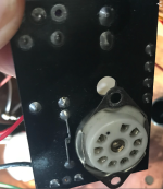
One thing that slightly confuses is me is the 4 Cathodes on the 6c45 valve, the connection is a 25R from each all joining into a shared 100R.
Could this be considered as 125R or 4in parallel being circa 6R + 100 = 106R
Sorry this is I am sure a dumb question 🙂
Rich
Could this be considered as 125R or 4in parallel being circa 6R + 100 = 106R
Sorry this is I am sure a dumb question 🙂
Rich
It's 106.25 ohm then, and the current through the primary of the transformer is further above spec then. According to this datasheet, all four cathode connections are internally shorted: http://www.r-type.org/pdfs/6c45pi-sovtek.pdf
That's probably done to reduce the inductance of the cathode connection. Irrelevant for audio, but for the UHF applications it was meant for, the cathode wire and pin inductance gives undesired series feedback. It's also the reason why the high-frequency performance of valves got much better when the manufacturers got rid of the pinch.
There is another way to connect the transformer that is specified for 18 mA. Are you sure that isn't used?
hi,
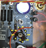
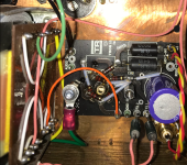
It's a while since I had it off the shelf and tried to undersand the circuit. The board acting for the driver is here, and at the time I concluded the capacitor was a cathode bypass, I am not sure exactly where the cap is connected, it's in a small repurposed circuit board, meant fro something else the builder made us of.
The wiring or the LL1660 is here, which I took to mean it was Alt S. Pink is from the B+ for the 6c45. Which I think measured 153V into the LL1660.
Rich
Attachments

Marcel has produced an impressive document, but I fear it may have gone a little over some readers' heads, so here is an infographic; the characteristic response of an inductor-loaded, underdamped triode. Damping of the resonant peak is covered in detail in Marcel's document, but in the OP's case I would just add a load resistor to the transformer secondary and call it a day!
Attachments

I have measured each cathode to GNDI guess I could also just connect all 4 cathodes directly to one resistor, and not have 4 small resistors to make the joint?
I saw this in another thread.
1,3,6,9 126,125,125,132 R
So I guess the 100+24R in series on each does actually translate to 124R on the cathode?
- Home
- Amplifiers
- Tubes / Valves
- Cathode bypass calculator help