I may have to retract my observation. Re-reading it, it can be interpreted that the P Mosfet is contributing 20% of output.
The sentence reminds me of a phrase that my father enjoyed repeating occasionally to point out how word arrangements matter.
It was "Throw the cow over the fence some hay."
The sentence reminds me of a phrase that my father enjoyed repeating occasionally to point out how word arrangements matter.
It was "Throw the cow over the fence some hay."
Hello generg,
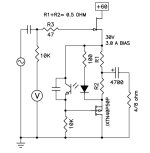
perhaps you could try to put the output between the first upper and second ( or the second and the third resistor?
Only a thought. Remember the 50W SE Schade -amp arrangement.
And I would think of an autobias -arrangement with 4N35 in the outputstage.
But this is my phantasy...
Greets
Dirk
perhaps you could try to put the output between the first upper and second ( or the second and the third resistor?
Only a thought. Remember the 50W SE Schade -amp arrangement.
And I would think of an autobias -arrangement with 4N35 in the outputstage.
But this is my phantasy...
Greets
Dirk
Attachments

Judging by this sounds like the power resistors on the puck pcb are degen resistors(to be able to lower mosfet gm) and the power resistors on the sit pcb are current sense resistors placed in the drain of the sit. The sit behaves better without degen at high power levels and low impedance loads.typically about 20%
You can look in the sim how much current each transistor contributes and adjust the mos degen resistor accordingly.

Hi Dirk, I tried the different resistor connections, no real game changer.
I have the feeling this time there is no 4N35....
I stop here and wait for better men! With more experience in electronics and LTspice.
:--))
I have the feeling this time there is no 4N35....
I stop here and wait for better men! With more experience in electronics and LTspice.
:--))
Tricky Pa
remember mention of some interesting biasing mechanism, plenty of things can be done in preceding stage, regarding modulation of output parts
anyhow, in this moment, I don't have enough details to guestimate too much
remember mention of some interesting biasing mechanism, plenty of things can be done in preceding stage, regarding modulation of output parts
anyhow, in this moment, I don't have enough details to guestimate too much
Gerd,
I am with Dirk re: speaker output between R29, R30, and also try between R30 and R22. Aim for about 30V or so at the speaker output. Try about 3A current.
Also 4N35 circuit for bias, or not, it's all guessing as Zen Mod said. 🙂
Check out my circuit: https://www.diyaudio.com/community/...mu-follower-amplifier-45w.371187/post-6623893
Last edited:
Whoa! This is the big one! Front end is very intriguing. Input cascode into unobtanium Toshiba FETs. That must sound quite special. Sure Papa sprinkled in some magic dust to optimize it and used the best parts possible from his mega stash to drive the SITs because of course they want the best. Four years in the making means it really is getting the most out of the SITs. It sounds like a giant killer and we’ll all want to build one 🙂
Merry Christmas all!
Merry Christmas all!

Steve Guttenberg contacted me about temporarily running them stacked, so I tested a pair that way and found the top one running at 3 degrees C higher, so at least it's not a short term reliability issue.

Are you gonna offer a couple at the BA25 auction?
I'll bring lots of cash this time... LOTS.
Merry Christmas Nelson! As usual so generous… thank you!Merry Christmas to all....
I was lied to all these years… Santa doesn’t live in the North Pole, he lives in the sea ranch!
Oh, wow, thanks for that awesome gift, Papa! It is Christmas indeed!
Yes.. Merry Christmas to all.
And a question. I see the 252SIT has a similar output? Or I'm I looking at this wrong?
I'm still hoping for a stable 50wpc into a 4 ohm SIT amp. Of ALL the amps I've ever had, and listened to, the 252SIT was the most transparent... it never sounded loud. It just played as a true wire with gain... until, well, Smoke On The Water, And Silence On The Sky... 😛
Still have six SIT transistors waiting for the day... I mean I could possibly use two bridged F4s and BA3 (or YIWDAF4), a Sissy SIT and the power resistors.... nothing like using a kilowatt of heat to get 100 watts... Cables, lights, boxes, switches....
$10K... gulp. That's approaching Pass Labs territories. Hopefully the stock market will move higher next year....
Last edited:
Seems pretty clear from the sketch, voltage gain from the front end, SIT is just a MU-follower, no gain, Nelson mention an easy 40W with this circuit at the SIT section. Seems to match the published pictures rather well…
Also the sketch shows that the feedback is limited to the front end section, and doesn’t include the MU follower SIT final section.
SB
Also the sketch shows that the feedback is limited to the front end section, and doesn’t include the MU follower SIT final section.
SB
Attachments
without third ( 4th, 5th..) confirmation source, I'm not eager to draw conclusions between simplified schm above, and fact that FW Products page is stating SIT 5 as No Nfb gadget
though, output impedance and THD figure are sorta confirming No Nfb scenario
That's Pa

anyhow - all guidances are there, World is our Oyster (again)
now, just make it not using scarce Toshiba TO92 and Toshiba small mosfets .......... and job's done
ambitious ones can even skip SIT, using Schaded N channel puck

though, output impedance and THD figure are sorta confirming No Nfb scenario
That's Pa
anyhow - all guidances are there, World is our Oyster (again)
now, just make it not using scarce Toshiba TO92 and Toshiba small mosfets .......... and job's done
ambitious ones can even skip SIT, using Schaded N channel puck
- Home
- Amplifiers
- Pass Labs
- First Watt SIT5