Update: If I take the bad channel out of the equation, then I get LED without flicker on the good channel and 10.1 V on its Q1
👍 that's good.
I want you to now check that this 'good' channel really is 100% good.
I'm also posting this image with typical voltages you should see.
1/ Does the preset adjust the midpoint voltage correctly? It should swing the midpoint a few volts above and below the correct value.
2/ This is an important one. Look at the arrowed test points. You can measure either to the resistors or to the FET legs (but be careful not to short anything)
Put one of your meter meter leads on one of the arrowed test points and the other meter lead on the other arrowed point. We are measuring the voltage between these points because it is more accurate than measuring to these points from ground.
Measured from ground we have 12.35 volts on one point and 11.43 volt on the other in this example. If you measure between these points you should see 12.35-11.43 which is 0.92 volts. That is the reading we want. 0.92 volts tells us that approx 1.58 amps is flowing in the FET's. Measuring between the points eliminate significant errors due to drifting of both voltages as the amp heats up.
(the voltages shown are all approx and will vary from amp to amp although the 24 volts should be a constant)
Mooly, sorry but how do I measure the Meanwell to see if it delivers a full 24V?
Measure to the middle leg of Q2. You should see 24 volts.
Sigh, and I thought that I had done a good job of soldering :-(
A couple of examples what looks like bad solder joints. To my eye there are more than the marked joints.
Now it seems that your problem is a short somewhere and not an open connection. But a bad solder joint can give problems later.
Edit: an open connection can also cause high current draw. An example could be a closed loop regulation that does not work.

Good!
Maybe quality check them all and ensure the solder pad is "nicely" filled with solder from the solder side.
Maybe quality check them all and ensure the solder pad is "nicely" filled with solder from the solder side.
Mooly,
From the middle leg of Q2 (red meter) to R4 (black meter) the reading is 13.6
From R2 to the end lead of R4 is 0.85
My voltmeter is set to 20V.
From the middle leg of Q2 (red meter) to R4 (black meter) the reading is 13.6
From R2 to the end lead of R4 is 0.85
My voltmeter is set to 20V.
From the middle leg of Q2 (red meter) to R4 (black meter) the reading is 13.6
That sounds OK. Q2 is actually the upper FET on the diagram so you are reading from supply to the midpoint but it cuts either way on this occasion and you would see a similar voltage voltage from ground to the R4.
So we say that is OK.
From R2 to the end lead of R4 is 0.85
Just to be clear, you are reading between these points. This is actually the same as from the middle leg of Q1 to the 'Source' pin of Q2 which is the one that goes to the resistors R1 and R2.
So 0.85 across the four resistors gives a current of approx 1.5 amp which is OK. The four resistors equate to a single 0.575 ohm resistor. I=V/R is 0.85/0.575 = 1.49 amp 👍
You should find both FET's equally hot (which is normal)
So DC wise that channel appears OK and it should play music normally if you want to try that.
Ok...things continue to be weirder. I have reconnected both channels. There is no more flickering of LEDs and the good channel works.
BUT the bad channel does now work, per se, for music.
IF I now measure from Q1 and ground on the bad channel it reads 23.9 volts, but the good channel has no reading.
I have zero idea what this means.
What does the resistor between the switch and the not good channel do?
BUT the bad channel does now work, per se, for music.
IF I now measure from Q1 and ground on the bad channel it reads 23.9 volts, but the good channel has no reading.
I have zero idea what this means.
What does the resistor between the switch and the not good channel do?
Can you take a fresh set of photos showing the connections and such?
That's fine.If I test the volts coming directly out of the mean well power supply, then it reads 23.9V
Good. That channel would appear to be OK then at this point.Yes. I can play music clearly through the good channel.
You need to be clear exactly what points you measure to. The FET has three terminals. The leg that goes to ground on Q1 is the Source. The middle leg is the Drain and the other the Gate.IF I now measure from Q1 and ground on the bad channel it reads 23.9 volts, but the good channel has no reading.
You may have a floating ground (not connected correctly) but we have to prove that.
So measuring from ground (and for this we will use that Source lead of the FET Q1 on the bad channel) you should see the 24 volt supply on the middle leg of Q1. So check that.
With the amp OFF you should read continuity between the Source of Q1 in each channel. In other the words the grounds of the two channels should be connected and have direct continuity between each other.
Some voltages to check on the bad channel:
1. DC voltage across R9: meter probes on each end of R9, what is the voltage?
Adjust the trimmer - does the voltage change? And can the voltage be adjusted to 4.5V?
2. DC voltage across R7: meter probes on each end of R7, what is the voltage?
1. DC voltage across R9: meter probes on each end of R9, what is the voltage?
Adjust the trimmer - does the voltage change? And can the voltage be adjusted to 4.5V?
2. DC voltage across R7: meter probes on each end of R7, what is the voltage?
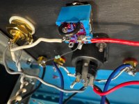
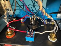
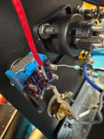
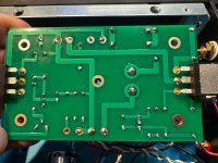
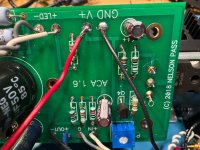
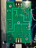
I am afraid I had no time to meter test anything today, but I did get a chance to take new photos as per 6L6's request. I start with the bad channel (a) bottom and top, and then channel (b), and then the back.
Not sure what can be gathered from the updates, but I did try to improve soldering as I went.
The one area that I am personally questioning is the back switch, as it seemed prone to not liking heat. Is there a simple way to check the switch or rewire it to avoid the switch altogether if it is broken or if that resistor is the culprit between the switch and the output tab?
Christmas is close!
Attachments
-
 IMG_6524.jpeg677.2 KB · Views: 64
 -
 IMG_6523.jpeg791.8 KB · Views: 66
 -
 IMG_6522.jpeg606.3 KB · Views: 62
 -
 IMG_6521.jpeg639.5 KB · Views: 68
 -
 IMG_6520.jpeg748 KB · Views: 63
 -
 IMG_6519.jpeg691 KB · Views: 66
 -
 IMG_6518.jpeg737.1 KB · Views: 70
 -
 IMG_6517.jpeg720.4 KB · Views: 66
 -
 IMG_6516.jpeg845.6 KB · Views: 62
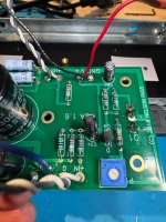
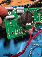
I still see solder joints that do nok look very "convincing". There are many. Below I just circled the worst my eyes found by a quick look.
It seems the temperature is not high enough so the solder flows naturally to fill out the whole solder pad and to get joints with nice shinny even surfaces.
The "forbidden" solder with lead content is the best to use as it has lower melting point that the modern "non lead" solder. The DIY Store "Fire Metal" solder is very good. If you solder on one side it is a good sign if the solder flows all the way through and have just filled out a little bit of the solder pad on the opposite side of the PCB. But sometimes the "fit" into the hole is so tight that it does not happen so not an absolute "requirement".
Meper,
Thanks again. I will go back over those specific joints. I am using Kester 60/40 solder and a Japanese Hakko soldering station.
Thanks again. I will go back over those specific joints. I am using Kester 60/40 solder and a Japanese Hakko soldering station.
60/40 is good if it is Tin/Lead. I use high temp and short solder time. I use around 420 C temp.
It also depends on the tip. It is it very small / thin it may start at like say at 400 C but when to start soldering it may be cooled down if there is not enough "heat reserve" in the tip (high mass). Relative short and wide tips are good for the ACA I think. There are a lot of space between most solder pads on the ACA PCB.
Solder irons like this has a lot of heat reserve and will not cool down very easy when used. But this is just a "wild" example.....
There was a vintage Danish brand called Danotherm as far af I remember that looked a bit like the below. They were very nice. Even the small 65W model 🙂
Hello there,
Sorry to jump-in with an odd question ...
When I was looking at the list of Forums, I found > "Pass Labs". Is this Forum a dedication to Nelson Pass, or does it mean something else?
IE. What does "Pass Labs" mean ?
Sorry to jump-in with an odd question ...
When I was looking at the list of Forums, I found > "Pass Labs". Is this Forum a dedication to Nelson Pass, or does it mean something else?
IE. What does "Pass Labs" mean ?
If you browse the forum, you will see that the topics are related to designs shared by Nelson Pass over time.
Preamp, power amp (Nelson’s fFirst Watt designs…),misc
Also, designs modified from Nelson Pass by others
You can check the correlation with https://www.firstwatt.com/articles-and-reviews/
Preamp, power amp (Nelson’s fFirst Watt designs…),misc
Also, designs modified from Nelson Pass by others
You can check the correlation with https://www.firstwatt.com/articles-and-reviews/
Last edited:
- Home
- Amplifiers
- Pass Labs
- Amp Camp Amp - ACA