Good digression, but the picture becomes even more murky for the tube amp output stage presented by the negative impedance effects of a reflex speaker with signals below system resonance, that is when the cone becomes unloaded below the resonance frequency as the air in port with lowering frequency changes phase to 4th order reponse. Most of us should know what happens to the cone movement when this occurs. In my early days I recklessly lost many a cone. Thus it becomes imperative that global nfb also reduces the effective output impedance that the amp has better control.. However, the effects of phase change relationship that loudspeakers present both inductive and capacitive to tube amps, which posess a low damping factor is complicated enough and a challenge to analyse.
So the clue to troubles ahead, that it is not surprisng that many tube amps do not like loudspeaker crossover networks. Give it a squarewave test, scope it and 60% of the waveform will probably look awful with under/overshoots hence we arrive back to the phase relationship what the tube amp sees and behaves.. Does it sound right ? May do, perhaps to our ears but electrically not. Thus the non inductive resister placed across the output terminals as a test element is barely representative of real life.
Philips back in the 1970´s ? tried the way out with SS with servo motional feedback. It sounded pretty good ...but quite artifical. Say no more.
Bench Baron
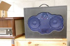
Almost 15 years ago I slapped together a pair of "test speaker" with one goal in mind. They needed to eat whatever I fed them without destruction and be made cheaply so that I wouldn't be too upset when I found their limits. This was during the time frame when I was extracting big power (125 to 250 WPC) from Pete's Big Red Board and I did not want to risk my Yamaha NS-10Ms. They were made with plywood that was "too thin" using a pair of 6 inch drivers that cost $22 each at the time (now $30). I added a bullet tweeter with an ON - OFF switch since I would play guitar through these and distorted guitar and tweeters are not friends. Shortly after making these speakers, I found myself doing the PA system for a friend's rock band at an outdoor show where they were fed by a 125 WPC version of the Engineers amp running at the edge of, and often into clipping for two days of near continuous use. "How do those little speakers get so loud?"
The poor speakers got to eat the full output of one of those discounted TI TPA 3255EVM boards until I thought that I had finally blown one of the drivers by playing bass guitar through it at full tilt to see how far I could launch a wad of paper that I stuffed into the port. Autopsy revealed no blown driver, I had just rattled the nuts that held the drivers loose. There are now two nuts on each driver. The speakers still work fine with the original drivers in them. I recently bought another pair for a bi-amplified guitar / bass amp project that will use an Eminence "450 watt RMS" driver for the low frequencies.
Oddly the Engineers Amp with no GNFB sounded quite good through these speakers. The class D TI EVB did not impress me with the same sound quality, but it was LOUD!
https://www.parts-express.com/Dayton-Audio-PA165-8-6-PA-Driver-Speaker-295-015
https://www.parts-express.com/Eminence-Professional-15-Paper-Cone-Woofer-3-Ohm-299-2251
Petes Engineers Amp at 250 WPC can be seen in post #218 here:
Hello all & happy labor day -
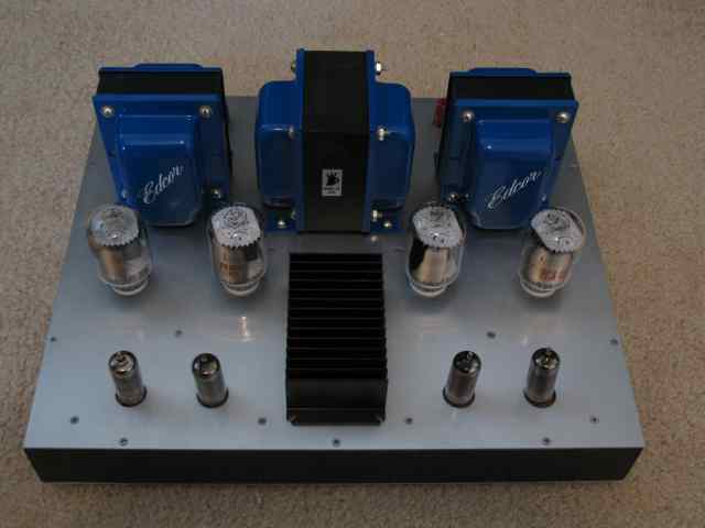
I just posted the design of a new power amp that I've been working on for some time.
This is a push-pull amp pentode using sweep tubes. Not screen driven (sorry SY) but pentode mode, with plate-to-grid feedback. Using 6JN6 or 6JM6/6GV5 tubes it does about 18W. Works with no global feedback, or with 6dB of feedback.
Drivers are also pentodes. The amp is set up to cancel some distortion between the driver and output stages (yes, it really does work!)
My goal was a practical and affordable amp. The...
The poor speakers got to eat the full output of one of those discounted TI TPA 3255EVM boards until I thought that I had finally blown one of the drivers by playing bass guitar through it at full tilt to see how far I could launch a wad of paper that I stuffed into the port. Autopsy revealed no blown driver, I had just rattled the nuts that held the drivers loose. There are now two nuts on each driver. The speakers still work fine with the original drivers in them. I recently bought another pair for a bi-amplified guitar / bass amp project that will use an Eminence "450 watt RMS" driver for the low frequencies.
Oddly the Engineers Amp with no GNFB sounded quite good through these speakers. The class D TI EVB did not impress me with the same sound quality, but it was LOUD!
https://www.parts-express.com/Dayton-Audio-PA165-8-6-PA-Driver-Speaker-295-015
https://www.parts-express.com/Eminence-Professional-15-Paper-Cone-Woofer-3-Ohm-299-2251
Petes Engineers Amp at 250 WPC can be seen in post #218 here:
Hello all & happy labor day -
I just posted the design of a new power amp that I've been working on for some time.
This is a push-pull amp pentode using sweep tubes. Not screen driven (sorry SY) but pentode mode, with plate-to-grid feedback. Using 6JN6 or 6JM6/6GV5 tubes it does about 18W. Works with no global feedback, or with 6dB of feedback.
Drivers are also pentodes. The amp is set up to cancel some distortion between the driver and output stages (yes, it really does work!)
My goal was a practical and affordable amp. The...
- pmillett
- Replies: 1,889
- Forum: Tubes / Valves

Attachments
Last edited:
Should load reactivity and back EMF be lumped together? I came across an article in AudioXpress that made me curious: https://audioxpress.com/article/back-emf-phase-relationships-in-moving-coil-loudspeakers-part-1
"The article also illustrates how and why the Back EMF at no time “drives” a current, but at most, shifts the phase of input current relative to input voltage, just as any reactive impedance."
"The article also illustrates how and why the Back EMF at no time “drives” a current, but at most, shifts the phase of input current relative to input voltage, just as any reactive impedance."
You are correct of being curious ! It is a bottomless subject. As I see it, an amplifier with good damping factor should effectively dampen the driver coil/motor back emf....however this isn´t always the case as with SE without global feedback one then gets LF hangover or boom bass. To many it sounds better and fuller. A clue to PP troubles ahead is examine the amp stability test, that is shunting the amp output with a cap and resistor, then often one sees horrible waveforms with a remark on phase agle effects. The following article was in early 1960 when simple 1st order crossover were around. http://www.tubebooks.org/file_downloads/moyle_amp.pdf It may seem out of date, but it really isn´t as since todays vendors continue to produce replica output transformers based on original circuits then one can assume sim issues today.
Short of being hijacked and put into another corner, in 1967 slide rule ability was rather cumbersome and slow, I´d thought studying for a higher degree in Loudspeaker physics, which is a heck challenging but instead I was attracted into the expanding military and space aspects of switchmode power and magnetics. For those with sim aptitude can read https://www.stereophile.com/content/book-review-high-performance-loudspeakers-seventh-edition but it ain´t cheap. However, a few years later as a serviceman (NATO), with a debut in microwave engineering, those were exciting but provocative cold war times as the over-horizon-radar DUGA was also a serious electronic countermeasure that interfered with nearly every communication and audio signal at that time. At 10MW it was immensely powerful and I recall most stage amplifiers, radio, hifi or live, that one would hear that "woodpecker noise" coming through. It was EMI at it´s best.
Bench Baron
I ordered some 100mA fuses to experiment with for connect the cathodes, the nominal (25C) resistance is 11 ohms. They are time-lag (or medium action):

The information that I got is that when the cathode becomes floating and is no longer able to conduct any current, that at that moment the grid will absorb the plate current as an alternative cathode, resulting in a destroyed tube.
This information may be wrong, but when true just inserting a cathode fuse may not be a sensible idea.
Hans
This information may be wrong, but when true just inserting a cathode fuse may not be a sensible idea.
Hans
Imho your information is wrong. Can you link to where you saw that?This information may be wrong,
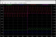
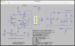
In the sim I added a switch that opened the cathode and it does look like the grid current goes up very briefly but it looks like it coming from the driver stage and is a function of it's output resistance. I did add a 51V zener across the switch to clamp the cathode voltage. I'm assuming when the fuse opens it's because the tube has runaway and the goal is to potentially save the output transformer. I think this would be the same scenario using a small wattage resistor as a fuse.
Attachments
For current to flow from grid to plate a grid would need to be hot enough to emit electrons AND at a considerably lower voltage with respect to the plate. That grid would also need a relatively low resistance path to ground for considerable current to flow. Most conventionally designed amplifiers do not satisfy all of these criteria so the usual behavior when the cathode loses its low resistance path to ground (fuse blows) is that the cathode voltage will rise to the point where it cuts the tube off (cathode voltage considerably higher than the control grid). There are two ways this can (and sometimes does) end badly. If the voltage rises high enough and the bypass cap is not in the fused circuit the cap may short and provide a path for current flow. If you fuse the cathode in a cathode biased amp put the fuse in the path of both resistor and cap. Another often overlooked failure mode is that the cathode voltage rises high enough for the H-K insulation to break down and feed the voltage into the heater string which may have a low resistance path to ground.
It is possible for a glowing hot screen grid to open a path for current flow from G2 to plate. This can easily happen in a sweep tube amp since the screen usually runs at 150 to 250 volts and the plate can be much higher. Yes, I have turned a few 6BQ6GT's into flash - bang grenades during my early screen drive experiments. Those experiments revealed the major drawback with screen driven amps that led me to discover the UNSET technology. No more exploding tubes and mosfets.
It is possible for a glowing hot screen grid to open a path for current flow from G2 to plate. This can easily happen in a sweep tube amp since the screen usually runs at 150 to 250 volts and the plate can be much higher. Yes, I have turned a few 6BQ6GT's into flash - bang grenades during my early screen drive experiments. Those experiments revealed the major drawback with screen driven amps that led me to discover the UNSET technology. No more exploding tubes and mosfets.
When I remember correctly, it was Euro21 who mentioned this in another thread.Imho your information is wrong. Can you link to where you saw that?
Hans
I didn't realize I can play wave files through a sim in LTspice https://www.analog.com/en/resources/analog-dialogue/raqs/raq-issue-175.html
George I just need a wave file of you tearing up the fretboard to destroy an amp and speaker 😀
George I just need a wave file of you tearing up the fretboard to destroy an amp and speaker 😀
Last edited:
Of course all current within the valve must come from, and thus "through", the cathode. Perhaps our discussion might turn towards the best DIYers' choice of possible cathode "fuses". One could argue that a 10R series'd cathode resistor should be included in all DIY, or even all repairs of antiques (?). What would be the best resistor type (let's call it 10R value) available in modern 1% tolerance to best act as fuse indended to save the OPT first and the output valve second priority?
Thanks, and all good fortune,
Chris
Thanks, and all good fortune,
Chris
Only some manufacturers make 1Ω MF resistors in 0.4W or 0.25W ratings, whereas 10Ω 0.25W is appropriate for cathode sensing to 160mA continuous (ie. class A, or 320mA with 50% duty-cycle).
Overload testing on some 0.6W MF MRS25 1Ω and 10Ω resistors showed they could still ‘function’ even when subjected to 15x their dissipation rating (ie. 9W, or 3A for 1Ω, and 1A for 10Ω), with the acrid fumes being an indicator of a fault.
Overload testing on some 0.6W MF MRS25 1Ω and 10Ω resistors showed they could still ‘function’ even when subjected to 15x their dissipation rating (ie. 9W, or 3A for 1Ω, and 1A for 10Ω), with the acrid fumes being an indicator of a fault.

Thank you for your always excellent work, available at https://www.dalmura.com.au/. One possible interpretation of the current state of the art is that 10R resistors (of any type or manufacture) might not be suitable to also act as a fuse - not their gig. So the question arises, is a 10R-ish resistor of some type capable of this double duty, current sensing and protection, or is some special series'd metal fuse needed for Best Practice? Also, do you have any comments on "flame-proof resistors" in this context?
Of course this is deep in the weeds, off book, you didn't hear it from me, please don't send lawyers, kind of WAG - but in that hypothetical, completely imaginary situation, where responsible adult prudent sober DIYers chose to install 10R resistors in series with cathodes of output valves for the dual purposes of current measurement and fusing, what should we choose? Let's assume (yeah, yeah) octal 7S (6V6/6L6 family, 6550 family) and related EL34 family.
It's almost surprising that this hasn't yet become an issue in our community, where modern production flakey valves and antique amplifiers, from an era of better yet cheaper valves and lower mains voltages, often collide. What are your thoughts on our best path forward?
Always the best,
Chris
Re-reading my last post, I really need to apologize. It sounded like I was putting the red dot on you, just because you're especially knowledgable about so many things. It's more probable that no one has actually investigated this issue, with our particular emphasis on preservation of antique technologies, and that relevant data just doesn't exist.
Maybe the conceptually simplest combination of a series'd resistor and a specialised metal fuse is our best choice. An open question with a lot of question marks (?)
All good fortune,
Chris
Maybe the conceptually simplest combination of a series'd resistor and a specialised metal fuse is our best choice. An open question with a lot of question marks (?)
All good fortune,
Chris
I don't know........maybe it would blow up the sim and take the computer with it.George I just need a wave file of you tearing up the fretboard to destroy an amp and speaker
In reality my 72 year old hands don't tear up the fretboard anymore. Nerve damage and pain in my left hand limits my playing time and ability. One of the doctors I talked to several years ago said that the pain comes from "too much guitar playing when I was younger in a manner similar to the pain caused by too much time pushing a mouse around a desktop." I have probably logged more mouse time than fretboard time in my life, but my right hand doesn't hurt. It does however drop things when I think I have them gripped tightly and guitar picks do have a way of disappearing from my hands. Note, dropping the soldering iron on your leg sucks. I don't wear shorts when soldering anymore. I still manage to solder my fingers almost every time I build something. The problem is that I smell it before I feel it.
I contacted Euro21, and this was his reply.
———————————————————
Hi Hans,
1.) Let's assume that the output tube has cathode bias (R//C) mode (the grid DC grounded via grid leak resistor and driving signal coming via capacitor) . When R or series connected fuse breaking, the anode-grid (very weak) diode start conducting and current will flowing trough grid leak resistor. If this resistor enough large, the very thin grid internal wire can survive.
2.) The output tube has fixed bias mode, the cathode DC grounded, the grid feeding via large resistor from negative bias voltage. The result is the same as in the previous case, if bias resistor is enough large.
3.) The output tube has "DC" biased mode, the cathode has R//C (or elevated DC voltage), the grid connecting directly to previous stage (DC coupling). The grid DC voltage is -usually- lower than the cathode DC potential (not in A2 mode).
If the cathode connection failed, the anode-grid diode start conducting. Because the previous (driver) stage has usually large -anode- current capability, due to the DC connecting, only the (output tube) anode-grid diode limiting the current flowing through, so probably the grid will blowing up.
Regards
Bela
Many people here know me as a person who likes to bow things up, especially tubes and tube amps or circuits. If it doesn't work, turn up the power supply until it melts, and I have a few HV supplies capable of 650 volts at 1KW! There are only three ways that current can flow from G1 (control grid) to the plate.
The most common in a somewhat working amp is a gassy tube that leads to a runaway condition. Once a runaway starts the tube is already dead and a fuse in the cathode can save other parts like the OPT. Usually by the time a tube gets bad enough to run away the amp is already quite distorted and should have been fixed.
A failure mode of some kind could have overloaded the control grid badly enough for it to glow red and thus emit electrons. This should have made the amp inoperative long before the grid got that hot. A glowing grid (G1 or G2) can and often does lead to some ugly stuff, but something has already gone wrong to make it glow.
An extremely overloaded tube can suffer a complete breakdown, and a tube arc occurs. This is like a lightning bolt from cathode to plate. When this occurs any number of possibilities can occur depending on what else blew. What causes a tube arc? Usually something must go really wrong to force some extreme current through the tube via the cathode to plate path. The resulting arc can put very wrong voltages on any tube pin including the heater. This usually destroys the tube and some surrounding circuitry.
Almost 7 years ago I was exploring the upper limits of some of my old tubes and pushed some old 6L6GA's a bit too far. Here a tube arc blew a chunk out of the side of a 1 ohm 2 watt cathode resistor. This happened twice when I was squeezing over 110 watts from a pair of old tubes that were never meant to be hammered this hard. Both time I just replaced the resistor, dialed back the power and cranked it up again. After two arcs I decided that 100 watts per channel was the limit. The fun played out here:
I have been playing with this board for about a month almost constantly, and I haven't blown anything up.....until now.
You would think that if I was beating on 70+ year old tubes with voltages far beyond the ratings while extracting power outputs in excess of twice the "typical operation" it would have been the tubes, but that does not appear to be the case. In reality I'm still not sure exactly what happened except for parts with chunks blown out of their sides.........
In the last episode I squeezed 70 watts out of some crusty old 6L6G's with no issues. I was cleaning up the lab, and...
Thanks Hans - #2 makes sense, I haven't looked at cathode bias just fixed bias.
Here is what I'm thinking:
Here is what I'm thinking:
- mains fuse in the power transformer primary in conjunction with a thermistor
- power transformer secondary CT to ground fuse (@trobbins method)
- cathode to ground fuse sized to protect the output transformer primary (as in post #1 schematic)
- a method to limit open cathode voltage to ground (not sure if this is necessary but seems prudent)
- if the heater has a CT which is grounded it should also be fused
- Home
- Amplifiers
- Tubes / Valves
- are cathode fuses a bad idea?