Watch out on that one.......Once I repaired an amp that suffered from high distortion caused by small film resistors in the cathodes gone "soft" and non linear when confronted with output stage leakage inductance overshoots. Don´t be tempted to do squarewave tests, this will gradually destroy film & oxide resistor types in such positions. These resistors have poor impulse capability when compared to wirewound which I always use.Small film resistors is linear until the moment they blow, and they blow instantaneously which a fuse does not.
( see "flame-proof" resistors that will not gutter the innards when flaming)
As for fuses in the center tap output tranny, even at 600V B+ this is against all the conventions as I regularly use 20mm plain glass Fast and never had a blowing or arc/spluttering problem and never had any shatter. A fuse shattered in a shielded holder is a horrible effort to get the glass fragments out. Perhaps the reason why I´ve never had any destructive issues is because I use a 1uF capacitor on the transformer CT side,
Horses for courses.
BenchBaron

The moral for thought:
I use fast fuses in the o/p center tap for maximum considered output stage current with a plus 20% tolerance for signal bumps and thump overloads. Testing an output stage into clipping below subsonic frequencies i.e o/p tranny saturation should blow. Clearly, much depends on the amp design that a massive DC thump on the inputs, which is bad design practice, and/or accidental shielded input earth going open has to be avoided. Build for tolerance.
Also a badly designed amp that is on the verge of motorboating into oscillation. With a o/p transformer fuse going open circuit, the hidden dangers of an unstabilized unloaded B+ can also rocket. However, a reason that I don´t get any of the problematic explosive fuse issues other users experience, is I use stabilized power supplies and that all important capacitor on the o/p transformer side.
For those wanting to use fuses, use UL fire retarded listed insulated fuseholders that require screwdriver for fuse carriage removal and not open chassis tong types, and importantly be aware of the high voltage dangers and use bleeder resistors.
Stay safe for Christmas.
BenchBaron
I do use 1 1KV fuse on the HT to each OPT for 6550 PP amps. But I do add a reverse diode from the CT of the OPT to ground to catch the big voltage spike. I did blow one with square wave. No drama, no glowing 6550 no broken OPT.
It doesn't look like anyone has prepared a detailed assessment of the likely fault clearing performance of a B+ feed dc fuse for an example amplifier and some common fault scenarios, and then compared that to the likely performance when fusing the PT secondary CT with an AC fuse. I've only done the latter assessment, as it allows common IEC fuses to be assessed, which are obviously easy to purchase and install along with an appropriate fuse holder.
Well fusing the primary side will protect you from 6550 developing an internal fault or loss of negative bias. It will protect the OPT and the cathode resistor and prevent the fireworks display that can sometimes occur. Certainly it can react much quicker to a tube fault. That is in addition to the normal AC fuse. A faulty 6550 can draw enough current to damage the OPT not so much as to blow the mains fuse. Hope this helps.
Trobbins is correct, this is unchartered terroritory.
I never use UL listed anti surge types whatever size for CT o/p transformer work as these have much more inner wound material and support structure that can easily create a DC glowing arc into a mess and here are the dangers. Obviously, the right fast fuse must be selected for the appropriate current pass, considering an AC fuse is being used for DC applications that aren´t specified in the manufacturers data sheets. If they are, then it is for a DC voltage level way,way lower. The other issue that many amp builders don´t realize, is the primary waveform of a push pull output stage with added winding parasitics i.e leakage inductance spike mixed in doesn´t resemble what one sees on the secondary, hence my reference to the capacitor on the CT side of the fuse to dampen the spike effects on fault. I assume the unlikely event that both tubes will simulantaneously fail at the same instant is rare; so an inner fault, i.e inner short circuit causing one side into instant core saturation or soft fireworks display.
As baudouin0 mentions, Le fireworks display; back in the early 1980´s I was unwisely tempted into some of the first Chinese made KT88s that appeared by Western vendors, and sure enough I did experience the oriental fireworks display from them, and it was this aspect that made me "do anything" to protect the output stage vitals.
Obviously, readers sussing all this out should realize and understand the dangers and limitations, not to mention any stray wiring inductance also plays a part, that can actuate any resonance situation on the instant of arc creation leading to dangerous conditions.
BenchBaron.
Having read through everyone's experiences, I am more convinced that Patrick Turner's strategy of powering off a relay when cathode current imbalances are detected is the best solution; shut that stable door before the horse has bolted.
I did a quick sim of 470V B+ driving a pair of 6550s with a A431 to 60W into 8ohms - the peak to peak voltage is almost 1.5kV across the OPT primary. I think I'll be very cautious with any sort of B+ fusing, I think @trobbins suggestion of fusing the secondary CT of the power transformer is worth exploring. Modern power supplies can have a large amount of stored energy compared to stuff from the 50-60s due to large low ESR high voltage capacitors, in a fault that energy will go somewhere and maybe not where I expected - I think I have a new view: more is not necessarily better concerning PSU capacitance.
Attachments
Last edited:
ESRC got a hundred of them in the mid 80's. After selling a few and having nearly ALL of them returned he sold me the remaining tubes real cheap, $2 or $3 each I think. This was the first time I ever saw a tube spark out on power up so violently that the glass broke! Most would red plate below 35 watts, some would hot spot at 20 to 25 watts of dissipation. I used some low buck guitar amp OPT's with these tubes but kept the power output to 35 WPC or less. Still over half the tubes would not live for more than a week of use. Now 40 years later I still have the two tubes that refused to die, and they were beaten hard in a 100 watt guitar amp running on about 500 volts. Really, two out of 100 isn't so bad? These tubes were being squeezed for all they had when there was a fireball on the bench. The OPT had burst into flames. Instantly I blamed the tubes but autopsy revealed that my test load made with four Radio Shack "noninductive 8 ohm audio load" resistors wired in series parallel on a heat sink had gone open. The tubes survived, the OPT was literally toast! I bought a pair of 8 ohm 500 watt resistors. Even I can't blow them up.back in the early 1980´s I was unwisely tempted into some of the first Chinese made KT88s
Attachments

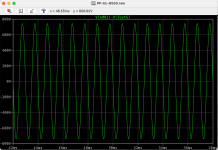
The resonance of a guitar speaker often falls within the range of the guitar, usually around 100 Hz for a 12 inch speaker. I scoped about 2500 volts peak on the plate of a guitar amp that ran a pair of KT88's on 430 volts cranked about 10 db past its clipping point. I was all over the fretboard and turned every knob on the amp looking for the highest peak voltage which was near resonance. Diming the amp (turning all knobs to 10) did not produce the highest voltage.the peak to peak voltage is almost 1.5kV across the OPT primary
I used a series string of 2 watt resistors from plate to ground with the scope across the bottom resistor. I don't remember the exact details but there are 7 150K 2 watt resistors soldered together in my junk box, so that was likely the test string. The actual voltage would have been a bit higher due to loading by the scope probe.
Can you elaborate on your sim please, as simple PP voltage would not exceed 2x 470V. Like Tubelab, I've been able to create conditions that force higher transient voltages than 2x B+, as a way of confirming the ease and benefit of soft-clipping those transients with a MOV across each half-primary winding - https://www.dalmura.com.au/static/Output transformer protection.pdfI did a quick sim of 470V B+ driving a pair of 6550s with a A431 to 60W into 8ohms - the peak to peak voltage is almost 1.5kV across the OPT primary.
Wrt fusing the power transformer secondary CT, there is a design method to determine an appropriate fuse rating, as well as assess likely fault duration until when the fuse blows - https://www.dalmura.com.au/static/Valve amp fusing.pdf
One of the most spectacular tube fails on live event was with an Ei KT90 which was used in a high powered amp (Manley??) .....it did short internally that any fault protection circuit (other than a fuse) would be too slow to react. At that instant the studio users noticed the instant of a very high pitched squeal, then all went quiet. Sounds like an external arc (no) or Tweeter zapped (yes it did) An external arc would have produced smells and smoke, so this was discounted.
Later on the bench, one can assume with one side of a push pull gone down, the other working instantly conditioned into oscillation, this instability is always a risk, but with my high powered amps which have large output trannies and relatively low bandwidth and highish leakage parasitics, I regulary use anode to anode RC snubbers to deal with ultrasonic issues. These also tidy up overshoots but these will also change the upper poles of any step correction networks. Again careful HV component selection and never use film or oxide type resistors for such applications. Wirewounds and kV rated caps only survive. The Manley output transformer survived but measurements indicated higher interwinding capacitances, which draws the conclusion of overheating windings. (write-off)
Like TubeLab, I also have some die-hard early tubes which appear to survive every bad event, but as I use SMPS for B+, the + bulk capacitances are just as high as per conventional, but more revealing is the very low output impedance created by the technology. So on a fault an enormous current demand on a good design is curtailed by current-cycle limiting which is very fast, but by then the Joules hold up time of the bulk cap has already written off any weak tube.
I see no real ideal way out of the protection dilemma without someone shouting "this is going to effect the sound quality". Apart from Bias protection stuff using comparators and integrators, which time-constant wise is slow, okay it might save the output tranny, but I am quietly "battening down my hatch" and remaining with the fuse option for the overall.
BenchBaron
Sure, and I realize I had the Stereophile simulated speaker load attached so it was a reactive load.Can you elaborate on your sim please, as simple PP voltage would not exceed 2x 470V.
Attachments
In class B the Vpp across one half-primary reaches 2*((B+) - Vak, min).as simple PP voltage would not exceed 2x 470V.
The Vpp across the full primary is twice that value.
"Vak, min" is the plate to cathode drop at the peak plate current. It is somewhat increased by UL operation.
Assuming a minimum Vak of 90V, the full primary voltage would be 1520Vpp.
Simulating an amplifier with a resistive load, or even a simulated speaker load with a single tone sine wave will not give you the true picture of what happens with real music being played through a real loudspeaker which can generate considerable EMF in resoinse to what just hit it.
Many years ago I tried to measure what a real speaker looked like to an amp when blasted with loud rock music. After going down a long rabbit hole with many side tunnels I wisely decided to climb back out never to return. Just ask yourself a couple questions.
What does the instantaneous input impedance of a large (I used a 12 inch) woofer's voice coil look like while playing a bass note at say 65.4 Hz when a rim shot on a drum transient tries to instantly reverse the cone's travel. I was convinced the impedance could indeed go negative as the back EMF generated by the mass of the cone + coil overcame the input current. Now repeat the same experiment with the rim shot reversed in phase.
A tube amp, especially one with low or zero feedback and a low buck OPT can exhibit unusual characteristics when driven to clipping into a speaker load. Ringing in the unloaded half (tube cutoff) of the OPT can generate a large transient spike in a cheap OPT.
I have a large quantity of cheap OPT's with no interleaving. They are wound from the core with one half primary, full multi tapped secondary, then the other half primary. With a good low impedance drive source like a pair of 300B's or fat sweep tubes in UNSET mode (local plate to grid feedback) these sound good. In a typical push pull amp they sound fair and can be made to misbehave.
I agree George - I have a 4kV scope probe and a pair of 200W non-inductive resistors but I think I'd need to build a Stereophile speaker load to get close to measuring anything for real. I think @Rikaro is correct about class B but I'm not a EE and typically math challenged, I rely on LTspice to understand things.Simulating an amplifier with a resistive load, or even a simulated speaker load with a single tone sine wave will not give you the true picture
-David
Completely agree - it's a balance between sanity and sanctity. I want things to fail in a semi-predictable way and I don't like catastrophic failures if they can be prevented. I think I'd put damaging an output transformer in the catastrophic category.I see no real ideal way out of the protection dilemma without someone shouting "this is going to effect the sound quality".
I am an EE, but also math challenged. I managed to pass all of the required math classes when I got my engineering degree at age 40 but flushed all of that stuff from my brain after getting a second degree. Many EE's over mathematify things to boost their ego. That stuff is needed if you are the guy that CREATES the simulation tool but not needed often for most EE design. The group I was in evolved from a circuit design team into an IC chip design team, so we had some kick butt simulation tools. I could take a first guess at a complex RF circuit play with it until it showed some signs of life, then give the tool some goals and some design constraints, engage the optimizer and go home for the night. The next day I would have a better working circuit, or a complaint from the simulator. Guess again, repeat. For $20K per seat per year it should build the proto for me, but, uh, that was MY job.I think I'd need to build a Stereophile speaker load to get close to measuring anything for real. I think @Rikaro is correct about class B but I'm not a EE and typically math challenged
The math he quoted is correct in a amp regardless of class to a certain degree. The plate voltage of a tube with its cathode grounded will swing from the point of tube saturation (minimum plate voltage when fully conducting) to about twice the B+ voltage. The type of tube used, how its configured, and its class of operation will control the saturation voltage. This is true only with a non reactive load which does not exist in real life. OPT imperfections, speaker resonance, and crossover component reactance create opportunities for unwanted behavior.
The "Stereophile" simulated speaker load might approximate the inductive reactances of a speaker, but it can't do anything about its electromagnetic action as a transducer which goes both ways. Applied electrical energy generates cone motion and cone motion generates electrical energy. That electrical energy gets fed back into the amp's output.
I started down the bottomless hole with a simple experiment. Connect an amp up with a signal source, preferably something that can generate tones and play various kinds of music. Connect a suitable resistive load to the amp, but this will need to be swapped to a speaker later. Put a scope probe on the amps input and output. You should be able to drive the amp to a reasonable level of undistorted power and adjust the scope such that the traces overlay on top of each other. Obviously, the output probe will need a higher voltage setting than the input. Some scopes like my old TEK 2232 have a switch to add the two channels and display the result. There is also an invert button for one trace which turns the addition into subtraction. This subtraction of the traces will remove the input signal displaying ONLY the DISTORTION. You should have very little on the screen at 1KHz and a low enough power level to stay away from clipping. This will likely rise as the frequency or power level is changed.
Now play some real music through the amp with the load resistor still attached. Ideally there should be very little displayed. Then connect the speaker and see what happens.
The next step down that hole involves a small (0.1 ohm) resistor in the ground leg of the speaker or load resistor. This can be used to see the current through the speaker and how its phase differs from the voltage over a range of frequencies.
No dual trace storage scope? It is possible now to grab both signals with a PC and sound card and record them with a DAW or Audacity for examination later. I have not gone far down this path yet, but it is being explored for guitar amp research.
- Home
- Amplifiers
- Tubes / Valves
- are cathode fuses a bad idea?