Like I said earlier; I rarely need to make accurate measurements for myself; I do almost ALL tweaking and fine tuning by ear. I was an Engineer and Technician but also a Musician. Those of us trained in music have what I consider an advantage in that we can "USUALLY" tell when the tonal balance is just right. In my case; the top octave and a half (starting around 8 KHz or so) needs to be increased so doing a measurement here for me in my listening space has very little meaning. Having said all of this; I do "sometimes" have to make accurate measurements just like most people do.
Even Vance Dickason remarks about art vs math and science some place in LDC. I can't remember exactly how he put it but personal taste means more to me than a ruler flat response. This is one reason I have each driver pair on it's own stereo amplifier; fine tuning! Besides, some recordings are overly bright, some dull, some have way too much bass, others; not enough...and so on...
[I'm excited once again; I have a new Crown amp on the way for the woofers. This will be a great advantage as it has built in DSP. I have a prominent room mode at about 40 Hz and THAT is very hard to fine tune. My sub has active bass management and now so will my lower woofers. I should be able to flatten out the low bass; the DSP has LP or HP or band pass with 1/12 th octave center freq.]...
Cheers!
oldspkrguy said "Those of us trained in music have what I consider an advantage in that we can "USUALLY" tell when the tonal balance is just right. In my case; the top octave and a half (starting around 8 KHz or so) needs to be increased so doing a measurement here for me in my listening space has very little meaning..."
Well said! I could not agree more.
I asked a pro sound guy once how he does it. It uses a RTA to set for flat response FIRST; THEN he fine tunes each and every venue he does by ear! Recording Engineers do the same thing; they trust their hearing. Musicians and other musically trained people tend to agree here as well.
I have a measurement system; and can and do use it from time to time. The science and math are real for sure but my idea is the whole point of DIY is to be able to tailor your sound to your tastes and liking.
Yes, all of these techniques are valid; there is more than one "right" answer.
I have a measurement system; and can and do use it from time to time. The science and math are real for sure but my idea is the whole point of DIY is to be able to tailor your sound to your tastes and liking.
Yes, all of these techniques are valid; there is more than one "right" answer.
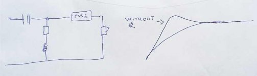
The placement was intentional, the smaller capacitor would bypass the resistor attenuation and provide a very high frequency boost equal to the reduction in level the resistor provides. The result is a HF shelf with the corner frequency determined by the capacitor, the smaller the capacitor, the higher the shelf frequency.I was curious to see in your little diagram that you have inserted a [quality] +/- 1uF capacitor to bypass BOTH the Resistor and the current Capacitor in one leap, in this arrangement.
Was this intentional?
I assume this helps pass through any high frequencies that might have [possibly] been limited by the first cap...?
This would give you a shade more VHF tweeter, with no more of the lower portion of the tweeter.
Art
Yes, that is a neat trick. I bypass inductors with resistors sometimes to make a more shallow rolloff in a LP. Not for BSC but to give a little more upper response to a mid or mid-woofer that may be on the dull side.
Using Caps on resistors is a similar kind of thing.
Using Caps on resistors is a similar kind of thing.
Done! My Tweeters are JUST RIGHT!
Just to close-off this thread with an actual outcome...
The final configuration included a 1.8-Ohm resistor on the R5 position, providing fractionally less attenuation than the stock 2.8-Ohm resistor.
Our MAGNAT All-Ribbon 6 loudspeakers now convincingly better every other speaker we own - and we own a few!
Of particular interest, all through the upgrade our MAGNATs have been driven by our [15W - into 4/6/8 Ohms] LEBEN CS-300F tube amp, from its [switched] 8-Ohm tap.
By comparison, driven from the 4-Ohm tap, the MAGNATs sounded dry, constrained and less fleshed-out, so there's a lesson there too!
Many thanks again to everyone who helped.
Season's Greetings... Cheers!
and to you as well...CHEERS...waiting on my new neighbor to get home from work; he just happens to deliver beer for a living so he brings me any damaged boxes...for FREE!!! If you haven't followed my thread on my 3 1/2 way...I agree with experimenting and measuring both but I usually get really close because I do trust my musicians trained ears!
It has been almost exactly four years since my last confession… post. 🤣
In that post, I had found a happy place with our beloved MAGNAT ALL-RIBBON 6 loudspeakers and had simply applied the best polypropylene caps (I could find) to the tweeter circuit – removing the 30-years-old+ 3.9uF electrolytics in the process – replaced the wiring and binding posts, added some cabinet dampening and zipped them back up.
[I see that I eventually reverted to the original crossover resistors, so I imagine that it was the introduction of the polypropylene caps in the treble that corrected the original tweeter clarity problems. Most interestingly, I still have the original electrolytic tweeter caps and they both still measure perfectly. There’s a lesson there…]
Still in regular daily use, the MAGNATs sound magnificent and have performed flawlessly ever since.
In the interim – in-between moving from New Zealand to China, raising our (now) 6-year-old daughter, and completing several other more complex hi-fi DIY projects – I recently returned to this project.
I now have some time to revisit these loudspeakers and will try throwing some exotic parts at them, to see if they can be further improved. With this in mind, it is my intention to replace all of the crossover components with:
V-CAP ODAM capacitors in the tweeter circuit
JANTZEN Cross Cap MKP capacitors in all (other) positions
MILLS 12W non-magnetic wirewound resistors in all positions
JANTZEN copper-foil air-core inductors in all positions
(I know many will think I’m mad. But to my mind, this makes more sense than investing thousands more on new loudspeakers that will probably be packed with lower quality parts than these…)
Taking the excellent advice from @system7 @revisorn @diyiggy and others – thank you kindly – I knuckled-down with PowerPoint and a whiteboard and attempted to formulate a schematic for this crossover, that I could share here.
I know that there are probably better ways to represent a crossover schematic of this type, but I think that it is all there. That said, I’m not 100% sure that I have it perfectly correct, so I’m hoping some kind soul might check my work.
My final task is to measure the unmarked inductor coils and add this data to the schematic, ready for ordering new parts.
One question I have at this juncture is: Is it possible to accurately predict the mH values of the (TBA) unmarked inductors, based upon the factors already provided in the schematic?
Note, I have not bothered to show L1 as an IRON-CORE inductor - as it currently stands - as I fully intend to change it to AIR-CORE. 😉

The Dayton DATS can also do that, although I'm not sure of product availability for OP.
https://www.daytonaudio.com/images/resources/dats v3 brochure.pdf
https://www.daytonaudio.com/images/resources/dats v3 brochure.pdf
Woofer typically has inductor infront of it.I can see that I have wrongly located the FUSE.
There may well be more errors...
The way you have tweeter connected it would burn. It needs capacitor infront.
If you are like most, depending on your age, you have lost another 2 to 6dB in the "tweeter range" in those 4 years:It has been almost exactly four years since my lastconfession… post. 🤣
Whether it makes sense to change parts you found "convincingly better every other speaker we own" is up to you, but I think the change in your 2020-12-02 "final configuration" to the 1.8-Ohm resistor on the R5 position, providing less attenuation than the stock 2.8-Ohm (?) resistor was probably the greatest change.I now have some time to revisit these loudspeakers and will try throwing some exotic parts at them, to see if they can be further improved. With this in mind, it is my intention to replace all of the crossover components with....I know many will think I’m mad. But to my mind, this makes more sense than investing thousands more on new loudspeakers that will probably be packed with lower quality parts than these…)
If the tweeter series fuse and holder have partially oxidized in the last four years as is typical, the resistance may have increased to near the change in value you implemented.
If you are now looking for additional clarity and detail, it might be now be time to implement the high frequency attenuation bypass we discussed in posts #75, 77 and 86:
Obviously, the component values in the above may not be what you ended up with.
At minimum, the positions of L1, L4, and C3 are incorrect, and the value of R5 is inconsistent from what you stated previously.I know that there are probably better ways to represent a crossover schematic of this type, but I think that it is all there. That said, I’m not 100% sure that I have it perfectly correct, so I’m hoping some kind soul might check my work.
No, it is not, and inductors don't change value over time, unless the insulation is burnt off.One question I have at this juncture is: Is it possible to accurately predict the mH values of the (TBA) unmarked inductors, based upon the factors already provided in the schematic?
Changing the woofer iron-core inductor to an air-core will increase it's series resistance or physical size considerably.
If you are still using the 15 watt LEBEN CS-300F tube amp, core hysteresis is not a problem, but a series resistance change may be.
Of course, changing the coil's series resistance would require changing capacitor values to maintain the same crossover slope and frequency...
Art
@weltersys
Hey, Art, many thanks for all this effort. Appreciated.
Yes, ongoing hearing loss no doubt plays a part in all of our lives. Whilst I take every care not to beat-up on my ears, it's not something I have much control over, so I march on regardless.
The tweeter fuse and its receptacle have not oxidised at all. It is in as-new condition - and I occasionally polish the fuses, so I have no concerns there. I know I need to revise the drawing of the fuse on the schematic.
As mentioned in my return post - #90 - in the end I did not stay with the 1.8R resistor value in R5. I reverted to the original 2.7R resistor value four years ago, as detailed in my latest schematic.
To be honest, I have all the tweeter extension, detail and transparency I could ever ask for with the MAGNATs - without any fatiguing brightness - I am just curious as to what more might be waiting to be revealed in the frequencies below.
Thanks for alerting me to potential errors in the schematic placement of L1, L4 and C3. I need to go back to the whiteboard on this, it seems. This stuff is quite tricky for the untrained novice.
I'm aware that changing the woofer iron-core inductor will require more real estate on the crossover PCB, but it is also true for the swap-out of the remaining electrolytics to MKPs, so it's something to be considered in combination.
Yes, we still use our LEBEN CS-300F (15W) tube amp - switching with our BEWITCH 6550 (KT88, Triode, 26W) hot-rod, which tends to be our daily runner. Having the LEBEN remain completely stock provides an excellent reference point against which to compare ongoing DIY upgrades on our BEWITCH.
Thanks for answering my question about calculating the value of the unmarked inductors. In any event, I will take the advise of you and @markbakk and measure them all - inductance and series resistance - regardless of any markings.
Woofer typically has inductor in front of it.
The way you have tweeter connected it would burn. It needs capacitor in front.
Thanks @adason. Appreciated.
Back to the whiteboard for me.
That schematic has many errors. If you needed to, the coil could be elsewhere in the box, and connected with speaker wire.@weltersys
Hey, Art, many thanks for all this effort. Appreciated.
Yes, ongoing hearing loss no doubt plays a part in all of our lives. Whilst I take every care not to beat-up on my ears, it's not something I have much control over, so I march on regardless.
The tweeter fuse and its receptacle have not oxidised at all. It is in as-new condition - and I occasionally polish the fuses, so I have no concerns there. I know I need to revise the drawing of the fuse on the schematic.
As mentioned in my return post - #90 - in the end I did not stay with the 1.8R resistor value in R5. I reverted to the original 2.7R resistor value four years ago, as detailed in my latest schematic.
To be honest, I have all the tweeter extension, detail and transparency I could ever ask for with the MAGNATs - without any fatiguing brightness - I am just curious as to what more might be waiting to be revealed in the frequencies below.
Thanks for alerting me to potential errors in the schematic placement of L1, L4 and C3. I need to go back to the whiteboard on this, it seems. This stuff is quite tricky for the untrained novice.
I'm aware that changing the woofer iron-core inductor will require more real estate on the crossover PCB, but it is also true for the swap-out of the remaining electrolytics to MKPs, so it's something to be considered in combination.
Yes, we still use our LEBEN CS-300F (15W) tube amp - switching with our BEWITCH 6550 (KT88, Triode, 26W) hot-rod, which tends to be our daily runner. Having the LEBEN remain completely stock provides an excellent reference point against which to compare ongoing DIY upgrades on our BEWITCH.
Thanks for answering my question about calculating the value of the unmarked inductors. In any event, I will take the advise of you and @markbakk and measure them all - inductance and series resistance - regardless of any markings.
@weltersys
Hey, Art, many thanks for all this effort. Appreciated.
Yes, ongoing hearing loss no doubt plays a part in all of our lives. Whilst I take every care not to beat-up on my ears, it's not something I have much control over, so I march on regardless.
The tweeter fuse and its receptacle have not oxidised at all. It is in as-new condition - and I occasionally polish the fuses, so I have no concerns there. I know I need to revise the drawing of the fuse on the schematic.
As mentioned in my return post - #90 - in the end I did not stay with the 1.8R resistor value in R5. I reverted to the original 2.7R resistor value four years ago, as detailed in my latest schematic.
To be honest, I have all the tweeter extension, detail and transparency I could ever ask for with the MAGNATs - without any fatiguing brightness - I am just curious as to what more might be waiting to be revealed in the frequencies below.
Thanks for alerting me to potential errors in the schematic placement of L1, L4 and C3. I need to go back to the whiteboard on this, it seems. This stuff is quite tricky for the untrained novice.
I'm aware that changing the woofer iron-core inductor will require more real estate on the crossover PCB, but it is also true for the swap-out of the remaining electrolytics to MKPs, so it's something to be considered in combination.
Yes, we still use our LEBEN CS-300F (15W) tube amp - switching with our BEWITCH 6550 (KT88, Triode, 26W) hot-rod, which tends to be our daily runner. Having the LEBEN remain completely stock provides an excellent reference point against which to compare ongoing DIY upgrades on our BEWITCH.
Thanks for answering my question about calculating the value of the unmarked inductors. In any event, I will take the advise of you and @markbakk and measure them all - inductance and series resistance - regardless of any markings.
- Home
- Loudspeakers
- Multi-Way
- Quick win: My Tweeters are too quiet!