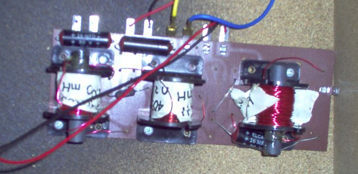
Mind reverse-engineering and draw the crossover's schematics? It isn't exactly rocket science 🙄.
And follow the hint given in #11, even when your tweeters aren't ferrofluid ones.
Best regards!
I'm obviously no rocket scientist...
 LOL!
LOL![But with a bit of help, I make up for that in tenacity...]
I've been studying the crossover - both sides - and to be honest, I haven't quite figured out which resistor is associated with the tweeter yet.
I had thought that C3 is the tweeter capacitor, given it's lower value, but I am evening wondering if I got that wrong now.
I have attached some more evidence and clues, if someone is willing to assist.
Attachments
Or a new kit of replacement FerroFluid for those tweeters 😀
Team,
Both tweeters on the current ALL-RIBBON 6 are working beautifully - and the speakers are fantastic - I'd just like more volume from the tweeter.
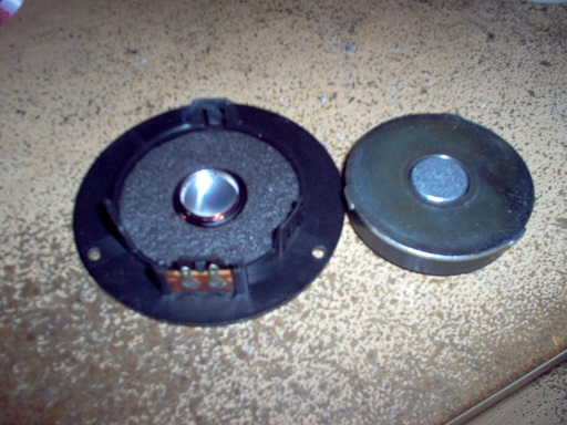
There just isn't anywhere to put fluid in this tweeter. It's just an open-back dome.
I own 5 pairs of these MAGNAT ALL-RIBBON tweeters and occasionally I lose a tweeter (dies...) which is why I keep a spare supply. I have moved tweeters from one pair to another several times with no problems.
I have had these tweeters apart many time but they are the devil to fix as the wires are thinner than a gnat's whisker. They never sound the same with a blob of solder in the final few millimeters of wire...
Have you considered an adjustable L-Pad? You could get a few cheap (25Watt) ones to play with. You can also use just 2 legs as a variable resistor. If you end up getting a higher output that you are satisfied with; you can then replace the cheap adjustable L-pad with higher quality fixed resistors.
Thanks for this suggestion.
I will go shopping for a variable resistor - just as you have suggested - if I can't find a quicker fix with the quality resistors I have lying around.
From my understanding the tweeter in the All Ribbon 6PII does have ferrofluid applied (is it the MHTL-28M?) but there are versions without also. You cannot swap them just like that by the way.
I have swapped identical tweeters previously and never encountered any issues.
Again, the current tweeters are working beautifully, I just want to raise their volume slightly.
There are no other issues with both current tweeters.
In general (assuming the tweeter is working correctly), if there is a resistor in parallell to the tweeter, raising the value with one or two ohms will raise the whole tweeter curve slightly. This will of course also change the transferfunction between the mid and the tweeter but maybe not so much. The other alternative is a whole new filter.
Thanks for this knowledge.
I recall many speakers - typically older or PRO audio designs - with feature an attenuation control. [Tannoys and the likes...]
I always assumed that this was just a variable resistor. Perhaps there is way more to it than this?
Anyway, on this basis, I figured I could reduce the tweeter resistor value a bit to achieve a slightly louder tweeter - say 5% - 10% louder - without messing-up the entire crossover.
Have I got this wrong?
Have I over-simplified things here?
There appear to be fuses in series with these tweeters, have you checked to make sure the correct ones are installed? Condition of fuse holders - have seen stranger things.
Have you measured the frequency response?
No. We do not have the equipment for such measurements.
Nevertheless, we own many pairs of speakers - MAGNAT ALL-RIBBON models and others - all of which provide greater tweeter presence, when all other system parameters remain static.
There appear to be fuses in series with these tweeters, have you checked to make sure the correct ones are installed? Condition of fuse holders - have seen stranger things.
Thanks Kevin. This is an interesting thought.
Obviously, the fuses are still working okay as all three drivers work fine.
But as you suggest, I will check the fuse value and see if I can find any "correct" specification with which to compare.
I'm sure that someone might encourage me to use a "Silver fuse"... 😀
@PeteMcK
Thanks Pete. That is my best guess too - provided that I’m right about C3 being the tweeter cap...
Thanks Pete. That is my best guess too - provided that I’m right about C3 being the tweeter cap...
Ferrofluid to be replaced?
You mention that you also have the same tweeter on a smaller speaker. Have you tried to swap them?
Ralf
I put my money on this being the issue. If you can get the tweeters apart, it will show immediately if the ferrofluid is a shiny, oil substance, or has deteriorated into a crumbling cake.
Sorry, I asked you to figure out the schematics, 'cause I am too lazy either to do it for you and additionally give you some hints.I'm obviously no rocket scientist...
[But with a bit of help, I make up for that in tenacity...]
I've been studying the crossover - both sides - and to be honest, I haven't quite figured out which resistor is associated with the tweeter yet.
I had thought that C3 is the tweeter capacitor, given it's lower value, but I am evening wondering if I got that wrong now.
I have attached some more evidence and clues, if someone is willing to assist.
Best regards!
HiFi Loudspeaker Design
Another calculator
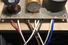
For MAX output, R1 should be zero (short) and R2 should be infinite (open). If you have a decent Ohm Meter, you should be able to figure out which resistor connects to what other component, drivers, etc. Of course, don't do this with the drivers connected. Carefully measure and make notes, make a sketch, place a label on each wire, etc. Make sure when you short the meter leads together, it measures zero Ohms (if not, you may be easily fooled by false resistance readings)
Another calculator
For MAX output, R1 should be zero (short) and R2 should be infinite (open). If you have a decent Ohm Meter, you should be able to figure out which resistor connects to what other component, drivers, etc. Of course, don't do this with the drivers connected. Carefully measure and make notes, make a sketch, place a label on each wire, etc. Make sure when you short the meter leads together, it measures zero Ohms (if not, you may be easily fooled by false resistance readings)

Thanks for this knowledge.
I recall many speakers - typically older or PRO audio designs - with feature an attenuation control. [Tannoys and the likes...]
I always assumed that this was just a variable resistor. Perhaps there is way more to it than this?
Anyway, on this basis, I figured I could reduce the tweeter resistor value a bit to achieve a slightly louder tweeter - say 5% - 10% louder - without messing-up the entire crossover.
Have I got this wrong?
Have I over-simplified things here?
Well, yes you got it slightly wrong, you need to increase the resistor value of the resistor in parallell with the tweeter in order to direct more energy to the tweeter. But if you havent done things as this before there is a big risk that things can go wrong and I advise against it.
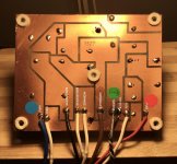
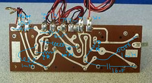
What you do here is copy the images into a paint program:

Now flip one of them left to right. You can see what goes where.
Then draw what is connected to what onto it with the pen. And label them best you can.
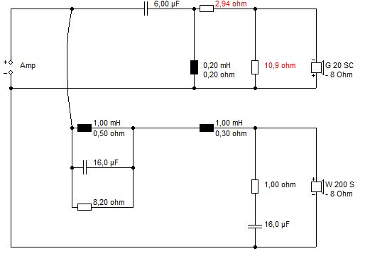
Easy enough to figure out the schematic.
This one was hard, but I got there:
https://www.diyaudio.com/forums/multi-way/314732-wharfedale-shelton-xp2-minor-classic-imo-2.html#post5429893
Now flip one of them left to right. You can see what goes where.
Then draw what is connected to what onto it with the pen. And label them best you can.
Easy enough to figure out the schematic.
This one was hard, but I got there:
https://www.diyaudio.com/forums/multi-way/314732-wharfedale-shelton-xp2-minor-classic-imo-2.html#post5429893
Well, yes you got it slightly wrong, you need to increase the resistor value of the resistor in parallell with the tweeter in order to direct more energy to the tweeter. But if you havent done things as this before there is a big risk that things can go wrong and I advise against it.
See my post 35. If you use an adjustable L-pad, you obviously must lift at least one lead on each resistor to take it out of the circuit.
I'm guessing the attenuation of your X/O is in the 2 to 6 dB range...UNLESS, for some reason the drivers have an unusually high sensitivity. Some fixed attenuators that use a switch and fixed resistors are set to give 0, -2 and -4 dB. Others; 0, -3 and -6 dB. This is "typical". So, yes, if you have the amp. up really loud after you remove all attenuators, you could damage a tweeter so proceed with caution. My guess is that this will NOT happen but better safe than sorry.
How hard can it be? 😀
I just contorted my brain round this crossover.
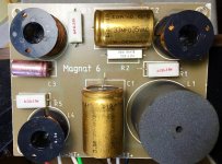
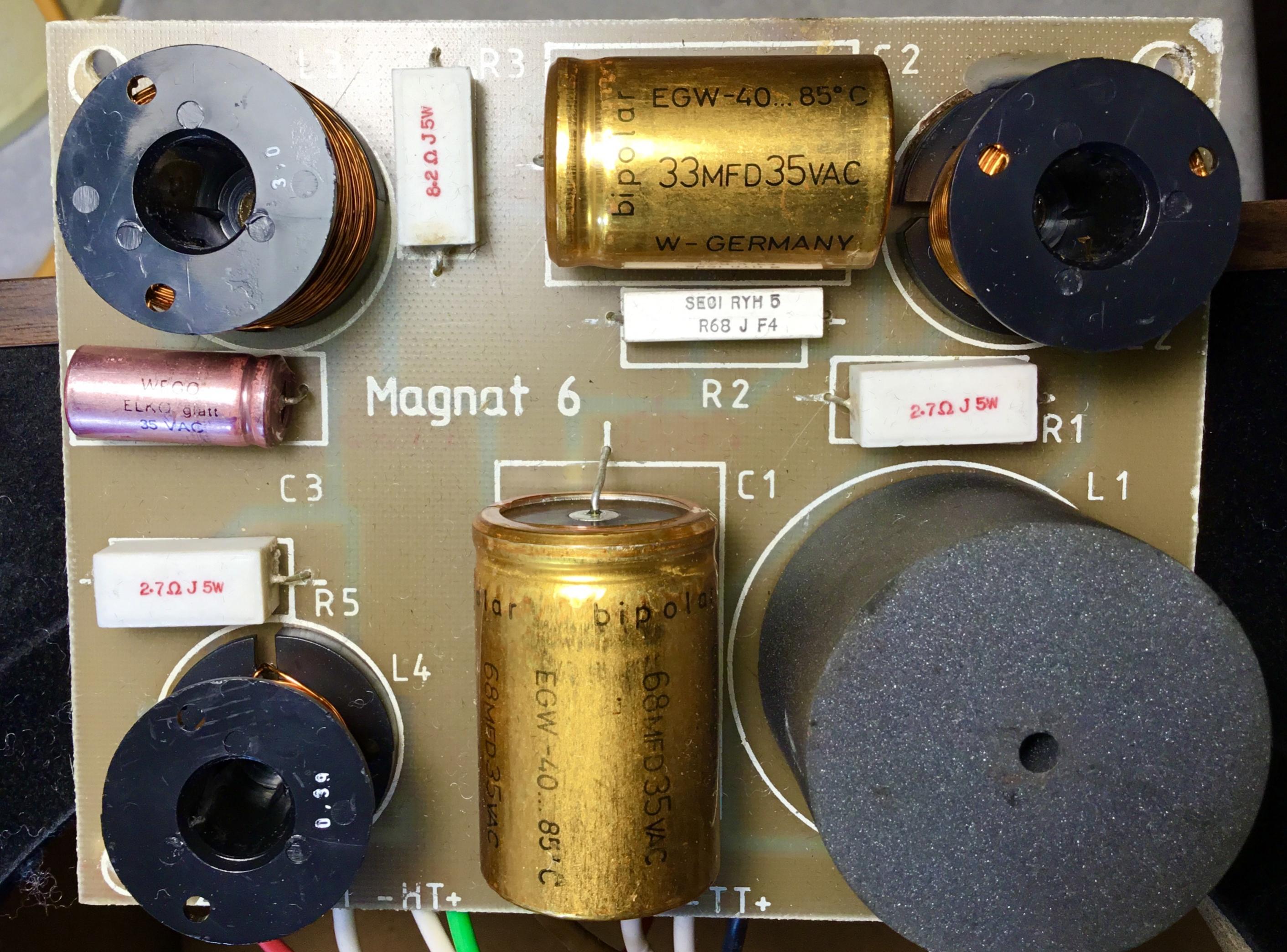
The L4 0.3mH coil bottom left is the right size for a tweeter section. The small pink C3 capacitor makes sense too and ought to be around 3.3uF. R5 2R7 must be the level adjust.
Like this simpler circuit:
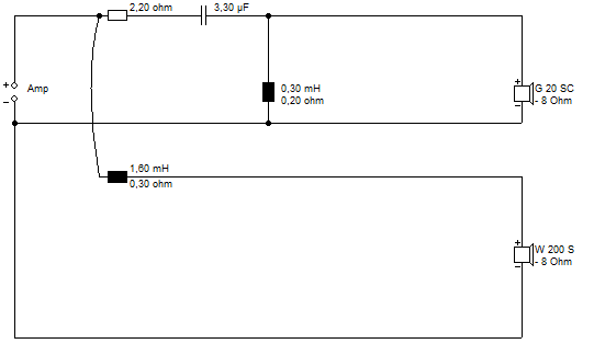
So you just reduce the 2.7R to, say, 1R for 1.5dB more loudness. Or short it out altogether as an experiment.
Ferrofluid is a possible culprit. I've taken it out of my tweeters with blotting paper. Sound better:
And as an afterthought, it might be worth cleaning the tweeter fuses if you haven't already. They can corrode.
I just contorted my brain round this crossover.
The L4 0.3mH coil bottom left is the right size for a tweeter section. The small pink C3 capacitor makes sense too and ought to be around 3.3uF. R5 2R7 must be the level adjust.
Like this simpler circuit:
So you just reduce the 2.7R to, say, 1R for 1.5dB more loudness. Or short it out altogether as an experiment.
Ferrofluid is a possible culprit. I've taken it out of my tweeters with blotting paper. Sound better:
And as an afterthought, it might be worth cleaning the tweeter fuses if you haven't already. They can corrode.
Last edited:
- Home
- Loudspeakers
- Multi-Way
- Quick win: My Tweeters are too quiet!