@maxellfullmon
You write, that no light in D-3.
D-3 is connected to the negative supply, so be sure that: 1. You have both + AND - 22volt into the boards.
2. That you have both regulators working, measuring +15v AND -15v on the most right leg seen from the front of 7815 and 7915.
I have a strong suspicion, that your negative supply is either missing or drawn down 😉
Your 1.3-1.4v over R27 should be in the range of 2,1-2,3 volt.

Boydk is right. I was overreading, that the LED doesn't light up.
If negative voltage is present and of correct value - check orientation of LED.
Greets
Dirk
If negative voltage is present and of correct value - check orientation of LED.
Greets
Dirk
@mhenschel,
Not sure if you're kidding or what. Nothing from the kitchen will be used in this build!
The is MILES above some infamous 25k riaa, and would withstand an hypersonic missile hit during shipping. 😎
Not sure if you're kidding or what. Nothing from the kitchen will be used in this build!
The is MILES above some infamous 25k riaa, and would withstand an hypersonic missile hit during shipping. 😎
kidding? only partly.
steel cookie tins are arguably better at shielding than aluminium alloy (I too love those cast enclosures from Hammond) and for two projects, I had tins on hand that happened to be of a perfect size and shape for the contents as I envisioned them. form followed function in serendipity.
for my Pearl 3 mounting the jack's in the lid meant I could easily open up the case to access the DIP switches. this might be trickier with a 1590-E as illustrated.
are your nylon standoffs different/ better than Tom's? just wondering...
I haven't heard any TEAD products. Have you?
The elephant in the room for me here is the wiring. I guess at some point in the past someone spread the rumor that using 8ga wire is a minimum in audio even to connect a pickup generating femto amps of current.I did have LEDs at first before I replaced the resistor at R27 and I had music, just sounded bad.
I think this build needs to be redone using max 22 ga throughout and shielded cable for the in/out. Twisting this wire generates undue mechanical strain of the connector and solder and other electrical contacts may come loose.
Last edited:
AFAIK steel is only better in shielding stray fields from transformers, sometimes it may couple the field and send it places you don' want it to go. I used steel shield in my M2x build around the edcor SUT as they were picking up noise from the power transformer.are your nylon standoffs different/ better than Tom's? just wondering...
Steel was a material I hated to work with as a teenager back in the 80s when I had no money for good quality Al cases.
Here I will use 3/8 diameter standoffs and 3" #6 stainless steel flat head screws. I normally don't go that beefy on stuff but this is a double decker and the length of screws I have around forces me to.
Yes, it will be infinitely stronger than the crap riaa helt together by spit and duct tape you're referring to. I'll post pics so you can 'roast my rig'. 😎
I just found it ironic that you were using nylon.
of course I'd be very interested -- in a very positive way -- to see your build....
before and (since you are making claims) after you drop it from the back of a truck without its proper shipping crate.
I understand that cast aluminium alloys are generally more brittle than other aluminiums.
My alternate enclosure would be fabricated from extruded aluminium shapes to match the case I'm planning for my BA2018 balanced line stage.
the bases for my ACA Redux balanced monoblocks would be sculpted 1590s.
TTA004B and TTC004B are correct. See Photo below.What I can't see: the two TOSHIBA TTA004B and TTC004B are not mistakenly in the wrong spot? But this is impossible - then your outputstage wouldn't bias up.
I checked continuity on all legs and they are good. I checked them against their corresponding mounting holes as you can see in the photo below.Most important for me: check soldering of JFets (Q1-Q4) - all legs in good contact?
I do have + and - 22 v to both boards but one thing is wrong with D3. When I first fired it up I had no LED lights on D3 but I did and still do have lights on D1 (both boards) but one of the boards the D1 LED is noticeably dimmer then the other. On the D3 LED I switched the wires from + to- and they came on I thought I just made a mistake. I have double checked this with a new LEDs and they now come on when I put the long lead to the - spot. So something is reversed?D-3 is connected to the negative supply, so be sure that: 1. You have both + AND - 22volt into the boards.
I do have +15 and -15 on 7815 and 7915 on both boards. I also checked and 7815 and 7915 are in the right position.2. That you have both regulators working, measuring +15v AND -15v on the most right leg seen from the front of 7815 and 7915.
The elephant in the room for me here is the wiring. I guess at some point in the past someone spread the rumor that using 8ga wire is a minimum in audio even to connect a pickup generating femto amps of current.
I think this build needs to be redone using max 22 ga throughout and shielded cable for the in/out. Twisting this wire generates undue mechanical strain of the connector and solder and other electrical contacts may come loose.
Yes, I wasn't too pleased myself with using that wire. I didn't have any shielded. I guess I could strip an old RCA cable.
@mhenschel
Ironic? Why? You just can't let go...
I am not stacking 7 boards on one another with 4 PLASTIC standoffs using #4 screws and hoping for the best. I reserve my judgement when I see your version, but, at face value, it may still be a step up from your cookie sheet solution. 😉 However, neither of us are not charging 25k quids for our builds either!
I have not tested my board but I compared to your pics I see nothing obviously different. The red LED 'seems' oriented like mine but I am not 100%.TTA004B and TTC004B are correct. See Photo below.
I checked continuity on all legs and they are good. I checked them against their corresponding mounting holes as you can see in the photo below.
I do have + and - 22 v to both boards but one thing is wrong with D3. When I first fired it up I had no LED lights on D3 but I did and still do have lights on D1 (both boards) but one of the boards the D1 LED is noticeably dimmer then the other. On the D3 LED I switched the wires from + to- and they came on I thought I just made a mistake. I have double checked this with a new LEDs and they now come on when I put the long lead to the - spot. So something is reversed?
I do have +15 and -15 on 7815 and 7915 on both boards. I also checked and 7815 and 7915 are in the right position.
Yes, I wasn't too pleased myself with using that wire. I didn't have any shielded. I guess I could strip an old RCA cable.
The cathode (=short leg) always goes to the flat side of the symbol; disregard + and - markings on the board as they are frequently for a neighboring part.I have double checked this with a new LEDs and they now come on when I put the long lead to the - spot. So something is reversed?
Have been following your issue and think you should pay attention to the odd fact that your voltage went down over R27 when you went to a 680 ohm resistor. It should go up at this time. 6L6 and Boydk will be able to address this specific error.
Here's an easy source to remember the LED orientation.
https://www.tips.modularparts.net/led-polarity-orientation-pcb/
alright friend, I just have some reservations in using such box. It’s about mechanical strength when inserting connectors.LOL, ironic... yes.
On my part l will try to cut back on the pesky double negatives in my comments..🥹
You're right. I see now the + was for C20 next to it.The cathode (=short leg) always goes to the flat side of the symbol; disregard + and - markings on the board as they are frequently for a neighboring part.
Have been following your issue and think you should pay attention to the odd fact that your voltage went down over R27 when you went to a 680 ohm resistor. It should go up at this time. 6L6 and Boydk will be able to address this specific error.
Here's an easy source to remember the LED orientation.
https://www.tips.modularparts.net/led-polarity-orientation-pcb/
Correct the LED orientation first; it may alter voltage readings in other parts of the board.You're right. I see now the + was for C20 next to it.
I almost soldered the led wrong myself due to the funny positioning of the + in the mask. Only by chance l noticed the issue in the guide.
@maxellfullmon
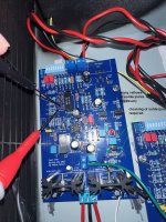
Looking closely at one of your pictures, it looks like you have installed D-1 wrong.
Might be bad resolution/blurry pic., but looks like the "flat spot" on the LED on the wrong side??
That is...... if the flat spot marking is indeed in the yellow circle. Please check and tell.

Looking closely at one of your pictures, it looks like you have installed D-1 wrong.
Might be bad resolution/blurry pic., but looks like the "flat spot" on the LED on the wrong side??
That is...... if the flat spot marking is indeed in the yellow circle. Please check and tell.
- Home
- Amplifiers
- Pass Labs
- Pearl 3 Burning Amp 2023