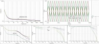
The topology is hidden in some proprietary module, and yes, it is that good. The noise and distortion specs are outstanding and would have qualified the amp as "laboratory grade reference amplifier"... if only they had installed proper heatsinking and a proper balanced input, that is...Is the B100 just a marketing gimmick or is it really that good? What is the topology in it?

Excellent! My expectation was the B100 like 50W max only. Now, it seems like 10W (continuous max drive). I would like to advise a friend who is still keen to buy one so I hope all will be good this way?
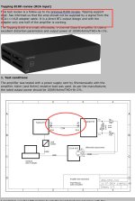
One thing I don’t understand is why the tester, Pavel configured unbalanced drive from the TRS (balanced ) output of D10 DAC that clearly states no true SE capabilities. And he is driving into the RCA input of the D100. Topping has clearly advised against this type of setup.
So the measurements of the/noise etc is a bit suspect. The correct way should have been balanced TRS from D10 to XLR balanced into D100
The use of USB isolator to possible overcome the loss of signal quality?
and if I were from Topping support I would dismiss this test arrangement and the report
So the measurements of the/noise etc is a bit suspect. The correct way should have been balanced TRS from D10 to XLR balanced into D100
The use of USB isolator to possible overcome the loss of signal quality?
and if I were from Topping support I would dismiss this test arrangement and the report
Attachments
Last edited:
Interesting to note that the B100 uses bridged output (BTL) with two amplifier circuits to get more output from lower supply voltage … and balanced input will be more optimal
… with BTL outputs, the damping factor will not be as good as other typical Amps with load to gnd types
Thanks Miero, very interesting but I am not quite on the same page:
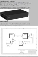
As I see it the the first setup looks not optimal as balanced output from D10 DAC (correct) configured on RCA wiring goes into the XLR input of the B100 with one end of the amplifier circuit grounded to match the SE drive (incorrect). So the THD+N figures not that good as one of the B100 amplifier circuit is not engaged.
So perhaps Topping advised Pavel to use the RCA input of B100 instead since RCA cabling and connectors were used. This is correct on the B100 side but Pavel had also configured the balanced out of the D10 as SE arrangement. This is not really optimal as the D10 is balanced out only and if signal taken from one line then the cmmr suffers so not optimal again.
Why not get Pavel to use TRS connections on both D10 and B100 and see how the measurements look like
Attachments


Are you aware that there are two Topping D10 models, the D10s with RCA outputs which Pavel used and the D10b with TRS outputs?One thing I don’t understand is why the tester, Pavel configured unbalanced drive from the TRS (balanced ) output of D10 DAC that clearly states no true SE capabilities. And he is driving into the RCA input of the D100. Topping has clearly advised against this type of setup.
The main requirement of a balanced input is to immediately subtract pin 3 signal from pin 2 signal and reference that difference to the local ground. If you need that output signal in both polarities to drive a BTL amp then you have to rebalance it again.
Topping did not follow this basic #1 rule of balanced interface technology, instead they fully amplify each input pin's signal individually and let the speaker perform the subtraction. And thus they rely on the output of the source being signal-balanced.
And It is not the first time as we saw simlilar issues with other Topping amps. Further, the B10b DAC doesn't implement a well-designed balanced output either because they made the exact same mistake. The DAC chip's output signal is balanced with quite some common-mode noise on in and normally you subtract these signals from each other to get rid of the common-mode voltage, then re-balance the signal again and thus allow to tap only one output pin and still get a proper signal with no distortion or noise penalty, just half the level. The B10b also has common-mode DC offset on the output.
The design effort and BOM cost of a proper re-balancer circuit in both cases is peanuts so that is not an applicable excuse.
This all clearly shows Topping does not understand what balanced interfacing is really about. I'm sure their designers were actually aware of the shortcomings but for some reason they were forced to implement those shitty half-baked circuits, if only to save a few cents or to speed up time to market or whatever....
My bad, forgot to see the fine print on the different models of D10🙈
So all good with Pavel’s tests so just back to power delivery issues
So all good with Pavel’s tests so just back to power delivery issues
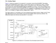
I don’t see why Topping’s implementation is bad on their DAC or Amp. See how AKM implements balanced outputs. The subtraction effect is at the output, very simplified with just one amp per line. Yes, you can sum and then rebalance but this means more active stagesAre you aware that there are two Topping D10 models, the D10s with RCA outputs which Pavel used and the D10b with TRS outputs?
The main requirement of a balanced input is to immediately subtract pin 3 signal from pin 2 signal and reference that difference to the local ground. If you need that output signal in both polarities to drive a BTL amp then you have to rebalance it again.
Topping did not follow this basic #1 rule of balanced interface technology, instead they fully amplify each input pin's signal individually and let the speaker perform the subtraction. And thus they rely on the output of the source being signal-balanced.
And It is not the first time as we saw simlilar issues with other Topping amps. Further, the B10b DAC doesn't implement a well-designed balanced output either because they made the exact same mistake. The DAC chip's output signal is balanced with quite some common-mode noise on in and normally you subtract these signals from each other to get rid of the common-mode voltage, then re-balance the signal again and thus allow to tap only one output pin and still get a proper signal with no distortion or noise penalty, just half the level. The B10b also has common-mode DC offset on the output.
The design effort and BOM cost of a proper re-balancer circuit in both cases is peanuts so that is not an applicable excuse.
This all clearly shows Topping does not understand what balanced interfacing is really about. I'm sure their designers were actually aware of the shortcomings but for some reason they were forced to implement those shitty half-baked circuits, if only to save a few cents or to speed up time to market or whatever....
Attachments
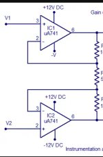
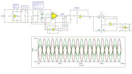
Not neccessarily. See following design example, a rebalancer/driver with high-Z inputs can be made with 3 opamps, even with switchable gains:Yes, you can sum and then rebalance but this means more active stages
The only restriction is that minimum gain cannot be unity.
A DC servo can be added with just one extra opamp. So you get away with 4 opamps for a full-featured amp input front-end.
Excellent! Yes, I have seen this elegant solution in new ESS 9039 DAC app (and also in Marcel’s RTZ DAC) but surprisingly Topping, smsl others seem to eschew this. I have implemented this 3 opamp arrangement on my new AKD39 DACs just to keep it close to ESS recommendations 🙂
Note that this is the high-Z instrumentation amplifier version, whereas in an I/V-stage one would use the FDA approach with current input, either as a fully integrated FDA or the 2-opamp or 3-opamp versions.Excellent! Yes, I have seen this elegant solution in new ESS 9039 DAC app (and also in Marcel’s RTZ DAC) but surprisingly Topping, smsl others seem to eschew this. I have implemented this 3 opamp arrangement on my new AKD39 DACs just to keep it close to ESS recommendations 🙂
While the INA with CM servo loop is nothing new it flew under the RADAR all the time and it is hard to find references. I remember to have seen an implementation in the late 1990's
Yes, it is more like the IA first stage. For the FDA/CM servo I don’t remember seeing anything like that during school days so was pretty stumped with Marcel’s and ESS ones.
Anyway, as a side note the Topping B100 have Gain=1 option also. This means less noise on the Amp side and all amplification from preceding low noise stages for even better overall S/N, SINAD😉
Anyway, as a side note the Topping B100 have Gain=1 option also. This means less noise on the Amp side and all amplification from preceding low noise stages for even better overall S/N, SINAD😉
B100 looks like an variant of ULD MK3 class B ultra low noise amp, released in SiliconChip magasine 2011?
https://www.diyaudio.com/community/threads/silicon-chip-uld-mk3-amp-0-0006-distortion.191674/
https://www.diyaudio.com/archive/blogs/comments/comment2715.html
https://www.diyaudio.com/community/threads/silicon-chip-uld-mk3-amp-0-0006-distortion.191674/
https://www.diyaudio.com/archive/blogs/comments/comment2715.html
- Home
- Amplifiers
- Solid State
- Topping B100