maybe "out of band" phase is actually important?
perhaps the extensive use of "Super Regulator"-class regulators has something to do with it?
as I said Magic Mark failing to examine the regulators more closely to see how they measure up to the usual suspects was a lost opportunity.
it would be interesting to have this phono stage, the Vendetta and a well-regulated Pearl 3 together for comparison.
Ken,
It’s not just the amp’s circuit diagram that determines the sound.
The PCB layout, the used resistors and caps, but almost more important the power supply or even split supplies for each stage that are all contributing to the final sound perception.
And don’t forget on top of that the psychlogical effect of testing a very expensive amp that can positively bias the reviewer.
The head of design from Cambridge Audio once gave 3 designers the same circuit design and let them realise this into a working amp.
The result?
Three different sounding amps.
Hans
For a first order minimum phase transfer function, the group delay, or simply the delay goes almost a decode beyond the point where the phase starts to increase.I see nothing unusual about the Mastergroove’s circuits to explain that assessment, that is, apart from those two unusual phase correcting measures.
So it makes sense to keep the phase for a first order minimum phase transfer flat to into the high audio frequencies.
But as you can see in #199, this does not apply for a second order system.
For the simulation I used a 6.5Mhz GBW LT1056 opamp.
For a faster opamp, without this topology a single ompamp would extend its phase far enough.
And for a slower opamp using the second order topology the extra delay will come into the high audio band.
But as always, the proof of the pudding is in the eating, so maybe you can breadboard this buffer and compare it to a single opamp.
Hans
Given that phono cartridge transfer functions start rolling off after the obligatory high frequency resonance around 20 kHz or so, with the attendant effect on phase response, I suspect the audibility of 0.5 microsecond delta in group delay would be literally lost in the noise.

@bogdan2011
It would seem that the video no longer speaks for itself. As I haven't seen it could you please provide a channel link so at least I can watch his other videos; I couldn't see any reference to the username of this youtuber so not sure what to search for. If this video is available elsewhere please please post a new link. Would be nice to see what's being discussed.
Thanks
"This video is no longer available due to a copyright claim by Tom Evans"
https://www.youtube.com/@MendItMarkI couldn't see any reference to the username of this youtuber
Very entertaining and skilled repair (and much more electronics) guy.
Boulder Amp says, “Hold my beer”:It’s the £25 000 price tag that makes it apparently sound better. Go figure.
Boulder 2108 Phono Preamplifier, $62,000.
https://boulderamp.com/products/2108-phono-preamplifier/Which, no doubt, makes it the mostest, bestest sounding phono stage! 🤩
Specs. Noise not specified properly and no overload info. Doesn't fill one with confidence. A lot of the other specs are fluff.

Excellent figures.
With 60dB gain this would result in only 65V output noise A-weighted.
Unfortunately the amp can only go up to 28Vrms. 🤣
Hans
With 60dB gain this would result in only 65V output noise A-weighted.
Unfortunately the amp can only go up to 28Vrms. 🤣
Hans
Fir the Boulder the literature says fully balanced throughout. It's difficult to see on the product images, but i can only see 2 wires connected to the xlr input? And the specs say converts to unbalanced? Not criticizing, just trying to understand.
Tom Evans has apparently filed a copyright claim on Mend it Marks video and the video isn't currently available anymore.
I must say this makes me a little bit angry and now hereby would kindly like your help to summon the Streisand effect..
Tom Evans might not be a multi-billion tech giant but I still think there is an important debate here to be had regarding right to repair, to share gained knowledge and information and if the copyright claims are even valid.
As far as I remember the phono-stage that he reverse-engineered in his video was exactly the same as any odd RIAA example circuit taken from a National/TI/BB audio opamp datasheet.
The most peculiar thing with the design from Tom Evans is that multiple gain-stages in parallel was used most likely to reduce overall noise as Mark also mentioned in his video - this is hardly copyright-able nor unique in my mind..
-C
maybe someone who also has (or had) a commercial interest in copyrighted material would like to chime in?
I recall that members who tried to post articles from Linear Audio had to take them down or had them taken down. Was Jan being unfair?
I recall that members who tried to post articles from Linear Audio had to take them down or had them taken down. Was Jan being unfair?
Well, that’s just too bad for Tom Evans and co., as I’ve already got some clear screen captures of the entire Mastergroove signal path. Although the individual component identifiers on the Lithos regulator screen capture are not legible, it still makes it possible to see the regulator topology and component types. From there, it’s fairly easy to figure things out well enough to build a close clone.Tom Evans has apparently filed a copyright claim on Mend it Marks video and the video isn't currently available anymore.
I must say this makes me a little bit angry and now hereby would kindly like your help to summon the Streisand effect..
Tom Evans might not be a multi-billion tech giant but I still think there is an important debate here to be had regarding right to repair, to share gained knowledge and information and if the copyright claims are even valid.
As far as I remember the phono-stage that he reverse-engineered in his video was exactly the same as any odd RIAA example circuit taken from a National/TI/BB audio opamp datasheet.
The most peculiar thing with the design from Tom Evans is that multiple gain-stages in parallel was used most likely to reduce overall noise as Mark also mentioned in his video - this is hardly copyright-able nor unique in my mind..
-C
To be clear, at least in the U.S., it’s not a copyright violation to use a schematic of a back-engineered circuit to build a device. Selling of the schematic is what is copyright protected, not the building of a physical circuit from it. As for patented circuits and other innovations, you are free to build the physical object, but only for non-commercial use. In fact, the government’s interest in granting patents is to encourage further innovation based off of commercially protected ideas. Experimentation/development is therefore encouraged. So, our DIY efforts are free and clear, at least, here in the U.S.
Last edited:
@Ken Newton
Well Tom didn't go after DIYaudio... us... he went after Mark who, it could be argued, sold the schematic to his viewers.
on the other hand, if you think you can do a faithfully performing clone it would be interesting to compare it to the super regulators we're familiar with in the DIY community.
it always seemed to me that the Lithos concept was a commercialisation of the notions that Walt and Jan were pursuing.
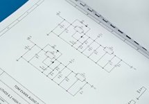
There seems to be two Lithos regulator topologies. A simple, higher power regulator formed by cascading an LM317 adj. and 780X three-terminal ICs identically for both the POS and NEG regulators. This is done so as to not utilize their negative counterpart devices, the LM337 and 790X, which perform worse. (Or, perhaps, they are the LM337 and 790X, I can’t read them.) This is fine, so long as separate transformer secondaries are utilized for each. The benefit of such cascading is the doubling of power supply rejection. This has been done many times before.
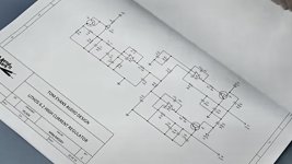
The other Lithos topology is more complicated, yet still doesn’t seem like anything unfamiliar, judging from my blurry circuit capture. It looks like a bipolar regulator utilizing NPN and PNP Darlington pass transistors, which are controlled by two op-amp error amplifiers. The one unexpected feature is the production of the voltage reference, where it looks like an LM334 type constant current-source feeds a resistor to produce a positive reference voltage. That voltage is conditioned by RC filtering, and then buffered by an op-amp. The output of the buffer is then utilized by both the POS and the NEG halves of the Reg. The POS half configured as a non-inverting amplifier, and the NEG half as an inverting amplifier. I’ve attached the blurry screen image I was able to grab.
The other Lithos topology is more complicated, yet still doesn’t seem like anything unfamiliar, judging from my blurry circuit capture. It looks like a bipolar regulator utilizing NPN and PNP Darlington pass transistors, which are controlled by two op-amp error amplifiers. The one unexpected feature is the production of the voltage reference, where it looks like an LM334 type constant current-source feeds a resistor to produce a positive reference voltage. That voltage is conditioned by RC filtering, and then buffered by an op-amp. The output of the buffer is then utilized by both the POS and the NEG halves of the Reg. The POS half configured as a non-inverting amplifier, and the NEG half as an inverting amplifier. I’ve attached the blurry screen image I was able to grab.
Attachments
Last edited:
- Status
- Not open for further replies.
- Home
- Member Areas
- The Lounge
- The £25,000 preamp that went wrong - Tom Evans Mastergroove