Hans, are you saying that the feedback loop-gains of each amplifier are summing, but without their open-loop gains also summing? So, for example, let’s say that at a given frequency, each op-amp has 100dB of open-loop gain, and then is set to 40dB of closed-loop gain. Leaving 60dB of loop-gain in each. That this topology sums the two 60dB loop-gain figures without also summing their 100dB open-loop gain figures? I feel like I’m likely misinterpreting what you are saying.
Last edited:
By chance, I stumbled across this short video showing the unboxing of a Mastergroove unit as shipped from Tom Evans. In short, it came packed in a plywood crate, not a cardboard box, and which features metal reinforcement of the crate joints. The internal packing material was merely bubble wrap, though.
When the loop gain of one single amp is 60dB at a certain frequency, it's distortion at that frequency will be reduced by ca. 60dB.Hans, are you saying that the feedback loop-gains of each amplifier are summing, but without their open-loop gains also summing? So, for example, let’s say that at a given frequency, each op-amp has 100dB of open-loop gain, and then is set to 40dB of closed-loop gain. Leaving 60dB of loop-gain in each. That this topology sums the two 60dB loop-gain figures without also summing their 100dB open-loop gain figures? I feel like I’m likely misinterpreting what you are saying.
When with this topology the second amp, working under identical circumstances also has 60dB loop gain, distortion will theoretically be further reduced by another factor 1000.
When both have 40dB loop gain at another frequency, distortion with this topology will be further reduced by an additional factor 100 for that frequency.
That's what we see here.
Hans

KSTR seemed to think that the distortion reduction was dependent on U1 and U2 having matching distortion spectra. Is that what your sim indicates, or is the reduction mostly dependent on the loop-gain, and independent of that matching?
Ken,
Tom Evans used a dual opamp and used the same load for both, which is important for the squared output current algorithm that KSTR used.
In practice parameters may differ slightly, probably attenuating the reduction effect.
As a matter of fact, looking in this case at the LR1056’s loopgain and comparing that to the reduction graphs I posted, the reduction is ca 15dB less as the loopgain.
But as mentioned before, when a single opamp at 100Hz has a distortion profile already below target, which will be the case in most occasions, this topology won’t bring any further benefit.
This may be different for the acoustical effects it has on the perceived sound.
Hans
I thoroughly enjoyed that.
Love his delivery style and attention to detail.
Thanks for posting.
Value is upto the chequebook holder!
Love his delivery style and attention to detail.
Thanks for posting.
Value is upto the chequebook holder!
I thought the primary justification for paralleling op-amps was improved noise performance? (Makes sense since this is a phono stage)<snip>
This may be different for the acoustical effects it has on the perceived sound.
Hans
Thanks, Hans. Higher gain applications, inherently having lower loop gain, would seem to most benefit from this topology.Ken,
Tom Evans used a dual opamp and used the same load for both, which is important for the squared output current algorithm that KSTR used.
In practice parameters may differ slightly, probably attenuating the reduction effect.
As a matter of fact, looking in this case at the LR1056’s loopgain and comparing that to the reduction graphs I posted, the reduction is ca 15dB less as the loopgain.
But as mentioned before, when a single opamp at 100Hz has a distortion profile already below target, which will be the case in most occasions, this topology won’t bring any further benefit.
This may be different for the acoustical effects it has on the perceived sound.
Hans
Kevin, Hans refers to the unique line-output amplifier topology. The schematic for which is attached in post #132.I thought the primary justification for paralleling op-amps was improved noise performance? (Makes sense since this is a phono stage)
Paralleling opamps gives a 3dB benefit in S/N bit, which might be useful at the input of a phono stage, but this topology differs basically from paralleling.
In this case it is situated at the end of the chain just after the Riaa correction, where op-amp noise is of insignificant importance, because according to the specs, this phono amp has 67dB gain when I'm correct, so the low noise stage before already amplified by some 36dB.
Hans
In this case it is situated at the end of the chain just after the Riaa correction, where op-amp noise is of insignificant importance, because according to the specs, this phono amp has 67dB gain when I'm correct, so the low noise stage before already amplified by some 36dB.
Hans
No Ken, the higher the loop gain, the greater the benefit.Thanks, Hans. Higher gain applications, inherently having lower loop gain, would seem to most benefit from this topology.
Hans
I meant, that since a higher closed-loop gain is closer to an amplifier’s open-loop gain, that leaves less loop-gain benefit as a consequence. In such case, wouldn’t the Tom Evans approach be of more benefit than for that same amplifier operated at a lower closed-loop gain, where it is more likely that there is already sufficient loop-gain? Which I had thought was one of your conclusions.
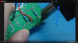
Apologies if this is a stupid question, but after watching him a bit, I'm mightily impressed with his desoldering tool, does anyone know what make and model it is?I'm watching this guy on YouTube that repairs all kinds of audio stuff
I think the video where he uses it is sped up, but it appears to have a marvellous hoover action - desoldering is one hurdle I always struggle with - and this video gave me new hope! 🙂
Attachments
Globulator: Have watched all the videos now and there are 3 desoldering tools Mark uses. A manual tool that sucks pretty well, a piston driven pneumatic with huge wires, and a modern automatic similar to the Hakko 301 (forgot the name).
If you become accustomed to the Hakko 301 you will never go back. It works like Mark's 3rd tool and makes major PCB alterations a much simpler process. Reviews on the web suggest a less highly priced version available on Amazon is also good.
If you become accustomed to the Hakko 301 you will never go back. It works like Mark's 3rd tool and makes major PCB alterations a much simpler process. Reviews on the web suggest a less highly priced version available on Amazon is also good.
The manufacturer recommends a bog-standard electrolytic after one of those regs; its ESR assures reg stability.
So it is beyond me why anyone would use a much more expensive polymer cap there and f*ck up the reg stability.
What are they thinking? Are they thinking??
I can't speak to polymer caps, but the LM78xx spec sheet says 0.1 uF ceramic post-regulator, while the lm79xx wants a 1 uF tantalum or a 25 uF electrolytic.
However, a glance at mouser shows the tantalum has 10 ohms ESR while the available electrolytics have anywhere between 0.4 to 7.5 ohms ESR. Which one is right?
Another thing, the cap immediately post-regulator is not the only one in the circuit: each opamp has 0.1 uF to ground on either supply line. Ten would bump the rated capacitance to 1 uF, with minimal PCB trace resistance, so that might want a look. If one wanted some ESR for the capacitors to keep the regulator from losing its mind then we're back to series resistance before each opamp bypass. Yes, we do lose some load regulation, but I don't lose sleep since PSRR is usually pretty good until about 100 kHz, and one could spec a bigger bypass cap with no ill effect since the ESL is almost identical between large and small units . I like using 3.3 to 10 uF hard by the opamps at a minimal increase in size & cost, and the impedance is below an ohm beyond 100 kHz until 10-20 MHz or so.
There is a range of allowed values. Normally the data sheet shows a graph of cap and ESR combinations and if you're inside the curve it's stable, if you are outside it is not.However, a glance at mouser shows the tantalum has 10 ohms ESR while the available electrolytics have anywhere between 0.4 to 7.5 ohms ESR. Which one is right?
As to other caps further downstream, these are isolated from the reg output by wiring R and L and do not figure in the stability.
It's all in the data sheets.
Jan
I've see commercial designs where those downstream MLCC's at the opamp stages wrecked the performance of a linear reg. While the designer hat correctly put a tantalum right at the reg he forgot about a bunch of MLCCs, maybe because of the circuit being on "downstream" pages of the multi-page schematic.As to other caps further downstream, these are isolated from the reg output by wiring R and L and do not figure in the stability.
The thing happily oscillated at ~30kHz. The wiring L and R was not large enough (physical distance was ~5cm).
But even if a circuit doesn't outright oscillate it could well be just marginally stable, with phase margins dipping way below 45deg, provoking severe ringing with load step changes.
Most datasheets of the classic "industry standard" types (78xx/79xx/317/337 etc) do not explicitly show the ESR range info because often the makers don't know the exact specs anymore, quoting TI on the LM317M:It's all in the data sheets.
"This LDO was developed back in 2000 so we don't have the full design data (including ESR range). But according to the datasheet, this regulator will be stable with ceramic output capacitors as referenced in section 8.2.2.2 of the datasheet. Having too low of ESR can potentially cause this regulator to have less stability (and hence, more ringing during transients) but it should remain stable."
ROHM is a notable exception with their BAxx series of regs.
I've see commercial designs where those downstream MLCC's at the opamp stages wrecked the performance of a linear reg.
Jan is correct in the case of one bypass after the regulator since the ESL and ESR of 1 mm wide trace over a ground plane is (IIRC) about 20 nH / cm and about 4 mOhm / cm so 10 cm of trace could help. However, if multiple bypass caps exist on a number of traces then the inductance and resistance are decreased due to parallel connection, and if the caps are on a single bus then the trace series impedance is dominated by the nearest cap's location, with impedance somewhat reduced by the other capacitors further down the line.
Most datasheets of the classic "industry standard" types (78xx/79xx/317/337 etc) do not explicitly show the ESR range info because often the makers don't know the exact specs anymore
TBH I'd be surprised if ESR range was known back then since designs tended to whack in tantalums and cheap & cheerful ceramics [1] which stood on longish legs, sometimes kinked (more inductance!) to keep them above the PCB, so problems never really arose.
In any event, regulators designed this century tend to behave better with capacitive loads, with the LT3081 datasheet positively encouraging designers to add low-ESR ceramics on the output, the more the merrier. The "Stability and Input Capacitance" section on page 13 mentions trace inductance forming a high-Q resonant tank with input capacitors [2], and in "Stability and Frequency Compensation for Linear Regulator Configurations" on page 14 this sentence appears:
Bypass capacitors, used to decouple individual components powered by the LT3081, increase the effective output capacitor value.
Now the LT3081/LT3091 aren't cheap at $8 to $9 vs $1.50 for LM7815/LM7915 at Mouser, but you get one fifth the output noise, maximum 36 volts input vs 30 volts, lower minimum load current (1-2 mA vs 5 mA), better ripple rejection across the spectrum, programmable output voltage, programmable current limit, and capacitive load independence. Given that folks can have a dozen of the latest not-cheap Wonder Opamps on their PCBs and drop a hundred bucks at Modushop for a nice box to hold them, an extra Jackson for decent regulation isn't over the odds.
[1] Ceramics also vary considerably in capacitance with DC voltage (a whole post in itself), which may have saved a few designs inadvertently.
[2] probably why LM78xx & friends datasheets recommend electrolytics or tantalums on the inputs
Last edited:
At least it looks like good bubble wrap. As long as there are no sharp edges on the amp, say, heat sink fins, that should work just fine. He could potentially save himself a lot of trouble by having some foam end caps made, though. That's what I do for my fully built amps. I also use a heavy duty box. The cardboard is 1/4" thick. You practically have to drive a forklift into it to puncture it.The internal packing material was merely bubble wrap, though.
I have the foam end caps made locally. They're not exactly cheap, but they're not exactly expensive either. I seem to recall paying around $400 for 23 sets last I ordered.
Tom
Several designs that oscillated at 30kHz?I've see commercial designs where those downstream MLCC's at the opamp stages wrecked the performance of a linear reg. [snip]
The thing happily oscillated at ~30kHz.
I don't suppose you have some measurements from those units?
Jan
- Status
- Not open for further replies.
- Home
- Member Areas
- The Lounge
- The £25,000 preamp that went wrong - Tom Evans Mastergroove