Its a Metcal MFR-1351 I believe. $$$$Apologies if this is a stupid question, but after watching him a bit, I'm mightily impressed with his desoldering tool, does anyone know what make and model it is?
I think the video where he uses it is sped up, but it appears to have a marvellous hoover action - desoldering is one hurdle I always struggle with - and this video gave me new hope! 🙂

There’s something interesting to note about the D.C. servo circuit on the line-output amplifier, schematic in post #132. On first glance, I thought it was a 2-pole implementation simply because it featured two RC networks, but it’s not, it’s single pole. On closer look it seems slightly strange, as the input passive low-pass provides all of the signal suppression, while the following integrator increases the D.C. open-loop gain of the servo, but essentially is unity gain at signal frequencies, providing no additional suppression.
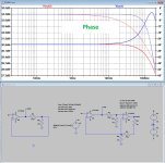
There is more taking place by the addition of the integrator, however, than just increasing of the servo’s loop-gain. Which, Tom Evans had briefly indicated in a cryptic comment about his servo in a published product review I saw. He mentions that the servo also corrects phase-error. Intrigued, I sim’d the servo to see what he could be on about, and it turns out that his servo completely flattens the varying phase shift due to the presence of the servo. Which otherwise progressively shifts phase 90 degrees below 10Hz. Evan’s approach renders that progressive shift perfectly flat, essentially, down to D.C. I can’t see how that would make a subjective difference, but it does prove Evans was telling the truth about his servo correcting phase.
There is more taking place by the addition of the integrator, however, than just increasing of the servo’s loop-gain. Which, Tom Evans had briefly indicated in a cryptic comment about his servo in a published product review I saw. He mentions that the servo also corrects phase-error. Intrigued, I sim’d the servo to see what he could be on about, and it turns out that his servo completely flattens the varying phase shift due to the presence of the servo. Which otherwise progressively shifts phase 90 degrees below 10Hz. Evan’s approach renders that progressive shift perfectly flat, essentially, down to D.C. I can’t see how that would make a subjective difference, but it does prove Evans was telling the truth about his servo correcting phase.
Last edited:
Years ago, I had a pair of LM317/LM337 with 10 uF X7R on their outputs. One of them oscillated. The other one didn't. 30 kHz sounds about right. It was somewhere in the range of 20-60 kHz. I forget which of the regulators was the oscillator. I put a tantalum cap in instead of the X7R and the circuit worked just fine. I used tantalum because I could fit it on the footprint for the X7R so I could make the change without changing the PCB. These days I use electrolytic cans instead.Several designs that oscillated at 30kHz?
I don't recall all the details, but I seem to recall that the amplitude was a few hundred mV peak-to-peak. Nothing earth shattering, but enough that I picked it up in the THD+N vs frequency plots, which made me go look at the power supplies. Someone who designs audio gear by ear would probably have missed it. Eventually it would have cooked someone's tweeter.
Tom
After Graigl59's suggestion I found this Silverflo model that looks like it will do the job for me, so I'll try to budget it in for Christmas, as an 'essential luxury' 🙂Its a Metcal MFR-1351 I believe. $$$$
https://www.ebay.co.uk/itm/296530171582
When i worked for Anritsu they had to send very expensive test-gear around the world, and they had a rather nice packaging system. One in fact that I want to replicate, somehow, to help a house move with my HiFi - so if anyone knows of such a system, please let me know..I was wondering, even when crated, would the nylon standoffs not shear off when dropped, despite the crate?
It's the shock that does it, no?
The system was that plastic bags were placed in the cardboard box, and pumped with a PU type of foam, around the test-gear box, which then set to a forgiving but static custom PU foam cradle.
I think the idea for shocks in that 2-3" of foam would lessen the G-force of the package below the point where something broke. I think they also added telltake G sensors in the box too, so they could find the max G force it has contended with !
Also wondering... Mightn't an impact that would shatter 1/2" acrylic also break PCB material especially if it was securely held by substantial metal standoffs?I was wondering, even when crated, would the nylon standoffs not shear off when dropped, despite the crate?
It's the shock that does it, no?
Jan
Perhaps an easily replaceable nylon standoff is better than a broken circuit board? I didn't see Mark having to repair PCBs.
Yes, over the years I've seen three designs with oscillating regulators in the 10s of kHz ranges, two were digital non-audio consumer stuff and the third one actually was an audio interface from a well-reputed manufacturer that I bought as an early adopter / beta tester. In that case I only reported the symptom of the issue and they reported back confirming the problem and that it was due an oscillating regulator. The also proposed a fix which I could assert and of course they updated production after that.Several designs that oscillated at 30kHz?
I don't suppose you have some measurements from those units?
Things go wrong at times, it will happen to everyone sooner or later ;-)
My experience matched the warnings from the IC designers back in the 80s. The 78XX were idiot proof, the 79XC were far more fussy and the low drop LM29XX families hated low ESRI've see commercial designs where those downstream MLCC's at the opamp stages wrecked the performance of a linear reg. While the designer hat correctly put a tantalum right at the reg he forgot about a bunch of MLCCs, maybe because of the circuit being on "downstream" pages of the multi-page schematic.
The thing happily oscillated at ~30kHz. The wiring L and R was not large enough (physical distance was ~5cm).
But even if a circuit doesn't outright oscillate it could well be just marginally stable, with phase margins dipping way below 45deg, provoking severe ringing with load step changes.
I can confirm this LOL, I've used these everywhere quite idiotically and they always work well.The 78XX were idiot proof,
The only drawback these days is avoiding fakes, and the dropout of course.
Not 30 kHz, but around 2.5 kHz is what I measured about ten years ago on a batch of PCBs with an LM337 in a certain industrial product that had been around like that for at least a decade, but only now made it obvious there had been a design flaw all that time. Previous products had not shown this stability issue during testing, but applying some freeze spray on the regulator could provoke some of them too.Several designs that oscillated at 30kHz?
I don't suppose you have some measurements from those units?
Jan
Wow! Alomost a volt! Horrible.
Did you find the cause? I suppose it is not related to output capacitor ESR, which was the subject of my earlier comments.
This looks like it is related to a too tight current limit setting.
Jan
Did you find the cause? I suppose it is not related to output capacitor ESR, which was the subject of my earlier comments.
This looks like it is related to a too tight current limit setting.
Jan
The cause was determined to be too low ESR of the several tantalums and ceramics that were strewn across the board. IIRC, a 0R1 resistor was put in series with the output of the regulator to deal with the instability and that cured the problem. I remember the PCB was quickly redesigned for this series resistor and some new designs incorporated it from the start.
The regulators were TO-263's supplying a couple of opamps only, so a too tight current limit seems unlikely.
The regulators were TO-263's supplying a couple of opamps only, so a too tight current limit seems unlikely.
The LM337 had a bit of a reputation for oscillating. The output was recommended to use a 1uF solid tantalum or 10uF aluminium. No mention of ceramic, so moderate ESR was assumed.
I tried once a LM317 and also LM337 as a CCS for AD162 Ge power transistor but both of these oscillates also and I couldn't stop it. Sadly I have no pictures because I went back to diode/BJT ccs, this one works well. Nothing to do with Tom Evans riaa , just an answer for LM317, but maybe Tom uses also LM317 in his preregulator ?
The system was that plastic bags were placed in the cardboard box, and pumped with a PU type of foam, around the test-gear box, which then set to a forgiving but static custom PU foam cradle.
https://www.ipack.com/C_49827/foam-...T-dv-krN4NZQjmBwWVdza7oou5uGrYTMFQT0LE__CqrP1
At any rate, it's an interesting circuit idea I have not seen before.
I now happened to find a reference to this circuit by chance and the original idea was to extend the bandwith of the phase response in stable way by using matched amplifiers, not the offset and general error compensation that comes with it.I further played a bit around with this intriguing topology.
Analog Devices, AppNote AN-107, Active Feedback Improves Amplifier Phase Accuracy, 1987.
http://www.t-es-t.hu/download/analog/an107.pdf
Side note: The strong peaking and thus marginal stability at low gains (like 2x) can be adjusted to the proper value (6dB) by adding an integrator cap to the second opamp. Likewise for very high gains a similar compensation can be added by introducing a zero-pole combo in the gain of the second amp.
So in fact the intention was not to reduce distortion, which already seemed a bit trivial, but to improve the phase accuracy at HF just like the servo seems to do at LF.
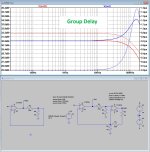
Maybe a look at the group delay could be also interesting, because phase doesn’t always tell the whole story.
Hans
Maybe a look at the group delay could be also interesting, because phase doesn’t always tell the whole story.
Hans
With this topology where phase accuracy is extended, the more important group delay for audio listeners is not at all improved,
Up to 20KHz, the deviation from group delay at 1Khz is almost equal for both, but at 100Khz, the single opamp deviates 0.2usec, where the second order feedback topology has a much larger 0.7usec.
So IMHO this seemingly phase advantage is of no advantage for an audio amp.
Hans
Up to 20KHz, the deviation from group delay at 1Khz is almost equal for both, but at 100Khz, the single opamp deviates 0.2usec, where the second order feedback topology has a much larger 0.7usec.
So IMHO this seemingly phase advantage is of no advantage for an audio amp.
Hans
Attachments
Intriguing. While Evans has stated what, he believes, is the importance of a flat phase, his design decisions, which increase circuit complexity, seem to bear his conviction out. However, and as you observe, those phase corrections take place outside the audio band. Take away those circuits, and what remains is a pretty standard op-amp based gain implementation.So in fact the intention was not to reduce distortion, which already seemed a bit trivial, but to improve the phase accuracy at HF just like the servo seems to do at LF.
Maybe a look at the group delay could be also interesting, because phase doesn’t always tell the whole story.
Hans
I find this intriguing, because published reviews of the Mastergroove which I’ve read, for whatever one may feel they’re worth, consistently mention how realistic sounding is its reproduction, and how it competes with or betters the best phono stage the reviewer has ever heard. I see nothing unusual about the Mastergroove’s circuits to explain that assessment, that is, apart from those two unusual phase correcting measures.
Last edited:
- Status
- Not open for further replies.
- Home
- Member Areas
- The Lounge
- The £25,000 preamp that went wrong - Tom Evans Mastergroove