As Jan alluded to, all that a patent does is give you the legal right to spend your own money to sue someone in court for commercial infringement. Patent’s also can be very useful to start-up companies in attracting both investors, and potential corporate acquisition suitors. Because patents provide the legal basis for protecting certain intellectual property rights, they help differentiate a company from its competitors, and thereby increase its market value. Which is especially important for technology based start-ups. Again, however, that all depends on having the financial resources to defend that patent from infringement in court.With all of the workarounds, patents and copywriting seem to be of little consequence. That is nothing new I suppose since the invention of fire.

Youtube tend to delete first, ask questions later.What is interesting is that it seems YouTube takes down material simply upon the "claim" of copyright infringement
In fact youtube routinely delete about 75% of my comments at random, I think I picked up a low 'social credit' score with them, around 2021 when Pfizer's marketing machine was at full bore, I also see others similarly targeted. Now I can't even comment about a valve spring adjustment, or a DPF pressure sensor without expecting it to be shadowbanned or deleted. It's quite bizarre, but follows the 'demoralisation' tactics of Bolshevism 101, so why they care about my harmless observations is known.
Tom Evans has been busy I think, perhaps because of the interest that Mark's rather amusing and delightful video raised - do an internet search of 'Tom Evans Mend it Mark' and you'll see, e.g:
https://hackaday.com/2024/11/14/repairing-the-questionable-25000-tom-evans-audiophile-pre-amp/
It seems many, many people saw Marks video 🙂
Having said that, There is no copyright being infringed, and I question the character of a man who wants to silence Mark, one of the nicest people around. Mark also spend a great deal of time and effort making that video, I hope he appeals to Youtube.
Nullifying Mark's time and efforts should carry a cost.
There's a few audio people who try to silence reviewers (or right-to-repair Mark), and it never ends well for them.
I understand some like to see it as a 'black art', but it's not, and often it feels that some are simply uncomfortable in the spotlight... which raises the other question: Why?
Indeed, this is how they should work.Because patents provide the legal basis for protecting
I listened to an interesting discussion about how the system actually works, about 8 minutes in here:
https://clifhigh.substack.com/p/the-other-physics
Thus confirming my lack of interest in obtaining any privately was wise 😀
In general they are a double edged sword, and can also be used by big corporations to prevent another Apple, the Steve in his garage now has a whole raft of patents to run into.
True, but not all op-amps feature such good PSRR across the audio band, especially against the negative supply, where I’ve seen PSRR spec’d. as low as 40dB for one current production op-amp.
That would be the NE5532 at 20 kHz, yes? The OPA1656 and OPA1612 are 30 dB better at that frequency.
The PSRR is always best at rejecting power line frequencies and its harmonics, not wide-band noise, hash and signal stage crosstalk.
Hence why I like low value resistors right before the bypass caps at the opamp supply pins. Since the trace between R and C will be de minimis, the least amount of potential noise will get coupled to the supply pins and the low pass network will eat whatever does get in.
Also, of course, not all gain paths utilize op-amps, whether good or bad performing. Simple discrete common-emitter/source gain stages, as you know, feature a 0dB PSRR, and very low PSRR if utilizing a triode common-cathode stage. Those circumstances make, so-called, super-regulators more useful. Though, with a great disparity in relative circuit complexity between the regulator and the gain stage it is supplying.
So long as a regulator has a few pins and a good spec sheet, I don't care if inside it has Benedictine monks singing Gregorian chants to null out supply gunge.
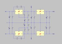
I made the circuit diagrams a bit more readable.There seems to be two Lithos regulator topologies. A simple, higher power regulator formed by cascading an LM317 adj. and 780X three-terminal ICs identically for both the POS and NEG regulators. This is done so as to not utilize their negative counterpart devices, the LM337 and 790X, which perform worse. (Or, perhaps, they are the LM337 and 790X, I can’t read them.) This is fine, so long as separate transformer secondaries are utilized for each. The benefit of such cascading is the doubling of power supply rejection. This has been done many times before.
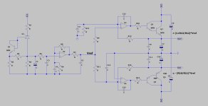
The other Lithos topology is more complicated, yet still doesn’t seem like anything unfamiliar, judging from my blurry circuit capture. It looks like a bipolar regulator utilizing NPN and PNP Darlington pass transistors, which are controlled by two op-amp error amplifiers. The one unexpected feature is the production of the voltage reference, where it looks like an LM334 type constant current-source feeds a resistor to produce a positive reference voltage. That voltage is conditioned by RC filtering, and then buffered by an op-amp. The output of the buffer is then utilized by both the POS and the NEG halves of the Reg. The POS half configured as a non-inverting amplifier, and the NEG half as an inverting amplifier. I’ve attached the blurry screen image I was able to grab.
The one with the LM317/LM337 like voltage regulators are doing a fair job in getting the rectified ripple very much lower.
The second circuit diagram first generates a very stable low noise Vref, and from there two +/- outputs are generated.
Hans
Attachments
It can be even more complicated.
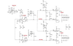
This is the supply from a ML36 Dac.
The two 7812 and 7912 voltage regulators are just for start up, but the +/-15V at the output is fed back to the opamps U5 thereby closing the loop.
Hans
The 10V on the lower U5 should of course be -10V.
This is the supply from a ML36 Dac.
The two 7812 and 7912 voltage regulators are just for start up, but the +/-15V at the output is fed back to the opamps U5 thereby closing the loop.
Hans
The 10V on the lower U5 should of course be -10V.
Attachments
Last edited:
A interesting approach to a boot-strapped start-up, Hans, with the start-up regulators disconnecting when their output diodes reverse bias upon the 5V reference, and the op-amps fully operating. Do you know the voltage and the source of the supplies feeding the complementary output stage?
Last edited:
Hard to imagine what they are trying to achieve here... seems an overindulgence in Splifs...It can be even more complicated.
This is the supply from a ML36 Dac.
They trying to achieve the same benefit that the Jung-Didden regulator provides, which is PSRR improvement via boot-strapping of the voltage reference and error amplifiers. As Bonsai correctly pointed out, that should be of no concern regarding regulator self-noise with the addition of the PSRR of typical op-amps. However, sometimes, there are relatively high level line-noise sources in addition the regulator’s self-noise. So, I guess, whether boot-strapping is beneficial or nor depends on the quietness of the power-line. In any case, I see this pursuit as no more pointless than the pursuit of amplifier THD levels to far under -100dB.
Last edited:
They are fed directly from the rectifier followed by large Electrolytics.A interesting approach to a boot-strapped start-up, Hans, with the start-up regulators disconnecting when their output diodes reverse bias upon the 5V reference, and the op-amps fully operating. Do you know the voltage and the source of the supplies feeding the complementary output stage?
I can't see the voltage, but the caps are specified for 35Volt, so I guess it must be somewhere between 20Volt and 30Volt.
Left and righty channel are completely separated, only connected by there analog gnd.
Hans
Sure. From a design perspective this can be interesting and fun but looks inefficient and convoluted, and seems questionable to achieve in any simplicity specific to performance attributes either electronically or sonically as bettered of a Jung-Didden approach. How far under -100dB do you estimate this is capable? That doesn't mean it doesn't work electronically or sonically in conjunction with other things not revealed.They trying to achieve the same benefit that the Jung-Didden regulator provides, which is PSRR improvement via boot-strapping of the voltage reference and error amplifiers. As Bonsai correctly pointed out, that should be of no concern regarding regulator self-noise with the addition of the PSRR of typical op-amps. However, sometimes, there are relatively high level line-noise sources in addition the regulator’s self-noise. So, I guess, whether boot-strapping is beneficial or nor depends on the quietness of the power-line. In any case, I see this pursuit as no more pointless than the pursuit of amplifier THD levels to far under -100dB.
The question still remains what are they trying to achieve? Is it just a high PSRR or is it a broadband ultra low Ro? Having recently listened to a preamplifier that had a connection for the addition of Farads of capacitance this may be what they are trying to do electronically, as there was a sonic benefit for adding such capacitance.
@Hierfi, “Sure. From a design perspective this can be interesting and fun but looks inefficient and convoluted, and seems questionable to achieve in any simplicity specific to performance attributes either electronically or sonically as bettered of a Jung-Didden approach. How far under -100dB do you estimate this is capable? That doesn't mean it doesn't work electronically or sonically in conjunction with other things not revealed.
The question still remains what are they trying to achieve? Is it just a high PSRR or is it a broadband ultra low Ro? Having recently listened to a preamplifier that had a connection for the addition of Farads of capacitance this may be what they are trying to do electronically, as there was a sonic benefit for adding such capacitance.”
_________________________________________________________________________________________________________________
It isn’t convoluted in approach, just in execution. In fact, it seems a rather straight forward, to me, dependable approach to boostrapped regulator operation. Utilizing a plentiful, reliable and inexpensive three-terminal regulator per rail to ensure start-up. It may appear convoluted, because of the complementary output stage design chosen, and related discrete constant-current regulator biasing. Why is that, because its a Levinson product, that’s why, and their engineers like to show off a bit. 😎 Which also ensures that customers don’t look inside the enclosure, and react the way many have in this thread to Tom Evans’ Mastergroove internals.
I was just arbitrarily using that -100dB figure, as a threshold which amplifier THD is routinely pushed further, and further beyond. Not as a regulator PSRR target to exceed. As far as Levinson design goals for their regulator, no doubt, they include both high PSRR, and ultra-low output impedence.
Last edited:
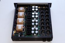
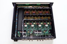
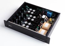
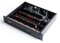
power supply for Borbely preamp and matching phono stage
100 watt R cores transformers
Quasimodo snubbed Hexfet bridge for each polarity and each phase
15,000 uf 10R 15,000 uf CRC filter - Diy Audio PC boards
16 Jung/Didden regulators now with jfet constant current source and leds for V ref - used as +/- 31 volt pre regulators for shunt regulators. ( even with custom 2 x 2 inch pc boards for the Jung regulators the chassis is still 21 inches deep)
Preamp
4 Discrete Jfet/Fet Borbely Shunt regulators +/- 24 volt
Balanced Borbely jfet/fet preamp
Built by Les Bordelon from boards I built.
Attachments
Last edited:
of course the question in the context of this thread is, if you put it in a plastic grocery bag and threw it off the back of a lorry, would it suffer any damage (let alone work)?
it was not a hypothesis to test!!
and we don't have Rob Ford around anymore to fix the crater in the road.
and we don't have Rob Ford around anymore to fix the crater in the road.
Opps,i thought thee pypothesis of this thread was how can you justify 25grand for a breadbin that states its exotic audiofilia. I bet even if you ripped out the grand worth of parts and pcbs it wouldnt keep my fave loaf fresh.
The open loop output has close to 2 ohms output Z. Far from ultra-low.they include both high PSRR, and ultra-low output impedence
Jan
- Status
- Not open for further replies.
- Home
- Member Areas
- The Lounge
- The £25,000 preamp that went wrong - Tom Evans Mastergroove