You'll want better decoupling if you want the amp to be stable near clipping, especially with 4 Ω load: https://neurochrome.com/pages/supply-decoupling
You can improve stability near clipping by adding an RC in parallel with R4. See AC Test Circuit #2 in the LM3886 data sheet.
Those things aside it's a capable amp.
Tom
You can improve stability near clipping by adding an RC in parallel with R4. See AC Test Circuit #2 in the LM3886 data sheet.
Those things aside it's a capable amp.
Tom

The lower pole is set by R5 and C6: fc = 1/(2*pi*R5*C6). I typically design for 2 Hz to ensure 20 Hz will be reproduced faithfully, so C6 = 1/(2*pi*2700*2) = 29.5 µF. The nearest higher standard value is 47 µF so that's what I'd use, though 100 µF would work too.
Tom
Tom
Thanks @tomchrYou'll want better decoupling if you want the amp to be stable near clipping, especially with 4 Ω load: https://neurochrome.com/pages/supply-decoupling
You can improve stability near clipping by adding an RC in parallel with R4. See AC Test Circuit #2 in the LM3886 data sheet.
Those things aside it's a capable amp.
Tom
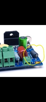
Another issue. The polarity of C6?
I am a little confused by this.
@tomchr Hi Tom, did you use an inductor on the input in your design? Would you share why , what value ? Also the output inductor value , zobel ?. Values from datasheet ?. Thanks.
- Bruno.
- Bruno.
Attachments

Yes it's confusing, it's a large value so it has to be electrolytic, but it has virtually zero volts across it. Long-term it's likely to lose capacitance. I saw a post on Audiokarma many years ago "My stereo amp lost bass" and "The feedback capacitor in that model always goes out, replace it."
Two fixes come to mind. One is use two capacitors of twice the value, in series with negative sides connected, with a high-value resistor from the negative connection to the negative power supply. This fixes the problem but may add a little offset from leakage current through the capacitor and resistor. I've seen this capacitor biasing technique used to allegedly reduce distortion in capacitors that would otherwise run at a DC value near 0 volts.
The other is use a non-polar (also called bipolar) electrolytic, as used in speaker crossovers. I never see these used other than in crossovers, and I wonder why, maybe there's something 'wrong' with them I don't know about, other than being a little more expensive.
Parts Express has a good range of non-polar values, and I'm a little surprised and amused to see both 47uF and 50uF.
https://www.parts-express.com/47uF-100V-Non-Polarized-Capacitor-027-352?quantity=1
Well. Let's do a little circuit analysis, shall we?Another issue. The polarity of C6?
This is the equivalent circuit schematic of the LM3886 from its data sheet. You can see the input is a pair of NPN emitter followers. The base current of that EF is the input current of the LM3886. Base current flows into an NPN, so current must flow into the LM3886 input.
If the output of the LM3886 is at 0 V DC, that must mean that the input current sets up a slightly negative voltage at the inputs to the LM3886. After all, DC cannot flow through C4 or C6. So the voltage across C6 is slightly negative.
So C6 really should be with its anode (positive terminal) to ground:
That said, it matters little in practice as the voltage is small. The typical DC offset for the LM3886 is 2 mV and the worst case is 10 mV. So there's no need for a bipolar capacitor or anything like that.
Yeah, but that's because the electrolyte dries out and the capacitor loses its capacitance. A bipolar capacitor or any of the other 'fixes' you suggest won't do anything for that. You could use a film capacitor, but a 47 uF film cap will be quite large. I'd just use an electrolytic cap. It's no more or less likely to dry out than any of the other electrolytic caps in the circuit.Long-term it's likely to lose capacitance.
Yes. 1.1 µH: https://neurochrome.com/collections/chassis-parts/products/output-inductorHi Tom, did you use an inductor on the input in your design? Would you share why , what value ?
The inductor is needed if you want the amp to remain stable even with a capacitive load. Think electrostatic speakers, long speaker cables, and such.
The Zobel network shown in the data sheet is a good starting point.Also the output inductor value , zobel ?. Values from datasheet ?.
Tom
That's part of the RFI/EMI filter. I have no idea of its inductance. Ferrite beads are usually specified by impedance at some frequency. I just picked one that had a high impedance. Not everything has to be rocket science. 🙂
The ferrite bead is followed by a ceramic cap to ground. 470 pF, probably.
Tom
The ferrite bead is followed by a ceramic cap to ground. 470 pF, probably.
Tom
Yeah. I put EMI/RFI filters on the inputs of amps. It's required if you want your amps to pass any sort of EMC compliance. It's also needed to avoid annoying clicks and pops from switch arcs, for example, when your fridge, furnace, or other heavy load turns on.
Tom
Tom
@tomchr Can you share what component values you have used in your design ? I know it can work with a wide range of values , But I'm curious in what you used , like values from the datasheet or something else , and if , why you used different values.
Like the input resistors, feedback , etc.
- Bruno.
Like the input resistors, feedback , etc.
- Bruno.
You can always buy a board from me. It comes with the full bill of materials.
Tom
Tom
Yep. The error correction in the Modulus-86 takes the performance to a whole new level.
Tom
Tom
Tom, I'm having this problem with my new amplifier. It's causing explosions due to items like refrigerators. I used the same filter but not the 470pf. What do you think I should do?Yeah. I put EMI/RFI filters on the inputs of amps. It's required if you want your amps to pass any sort of EMC compliance. It's also needed to avoid annoying clicks and pops from switch arcs, for example, when your fridge, furnace, or other heavy load turns on.
Tom
Attachments

I know you asked Tom that question, but what is your final schematic?
- Home
- Amplifiers
- Chip Amps
- LM3886 A great little Amplifier