I agree. The plywood I used was very cheep and therefore soft. So I think the next step is to repeat with much stiffer outer skins. And the urethane I used is 70 shore A, but I read that 30-40 is more effective. And I read that Geddes added silica spheres to his, so there seems to be a lot of room for experimentation-6db is not bad at all but from what i've seen it's possible to achieve way more when 'optimised'
How about some finesse instead of Dynamat?
I think you're reading too much into the initial experiment. I'm just gathering data!
The initial data is about validating the test method. My subjective opinion was that Dynamat didn't do anything, but this test showed that I was completely wrong. Another person posted that he sometimes used dynamat (or equivalent?) inside cabinets...I thought that would be a waste of time. But his choice is validated by my data.
This initial testing simply confirms that the test method is valid. The results show a trend that confirms what we already know.
And my first, low effort attempt at a CLD panel performs slightly better than a solid panel that is 30% thicker! So this is a success because it proves to me that this is doable.

I'm having decent results with FlexPaste, which dries to something around Shore A 30 to 40. You really want a toothed trowel like this or this to spread the stuff. Preparing the surfaces with 40 grit on an orbital sander would help the FlexPaste adhere better, too.
I've only tried the square notched trowel, but I suspect V notches might do a better job since the top of the material will squish down more easily.
I've only tried the square notched trowel, but I suspect V notches might do a better job since the top of the material will squish down more easily.
I've only tried the square notched trowel, but I suspect V notches might do a better job since the top of the material will squish down more easily.
How are you constructing your cabinet? Are you building a box from a single layer and then applying another layer to the outside of the box, gluing it with the flexpaste?
Or are you gluing the 2 panels together first, and then creating the box from the assembled CLD panels?
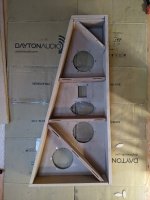
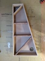
Inside the front panel looks like Picture 1, so where it doesn't have braces speakers are there to take up the slack. The rear panel touches those braces as in Picture 2. Note those are the same braces, overlaid on the front and back panels to show where they go. The item is 5.5 inches (140 mm) deep on the outside, 4 inches (102 mm) on the inside to provide optimum volume for the mid drivers so the sides really don't need much damping apart from what the internal braces provide. The back, however, is a bit live so I'm simply slapping another 3/4 inch (19 mm) of MDF with 1/8 inch (3 mm) of FlexPaste between the box and the panel, moderately clamped until the stuff dries, then clamped hard with dowels around the periphery for edge stiffness and keeping pressure on the FlexPaste.
Attachments
Here is Bon's thread about his built.
He detailed his construction technique. Intimidating to me and a masterpiece project imho.
He detailed his construction technique. Intimidating to me and a masterpiece project imho.
This is a report on my latest speaker project which has occupied most of my free time over the last six months. Since I am getting on in years, I expect this will be my last serious speakers, but I always say that. Typically I get about 10 years before the itch becomes intolerable and I have to scratch it again. Since my speakers are getting more massive as I get more feeble, this may well be it for me.
I went for top grade drivers, Scanspeak Tweeter D2904-710001, Scanspeak 6.5” Mid-Woofer Revelator 18W8531G00, twin Peerless 10” Woofers P830452. I want to crossover the mid quite low...
I went for top grade drivers, Scanspeak Tweeter D2904-710001, Scanspeak 6.5” Mid-Woofer Revelator 18W8531G00, twin Peerless 10” Woofers P830452. I want to crossover the mid quite low...
Would you mind some further details? Let's dump MDF as a suitable substrate for FRP sandwich first. It is very heavy and light and stiff is desired
Ply thickness?
Which carbon cloth?
Cloth type is very important. As is the stringer matrix as spans increase. So is the fillet at the junction of two panels
I've been thinking more about your comments, and I guess I sort of understand, but at the same time, I'm not sure if I do. I sort of understand the idea of vibration in structures as it relates to material fatigue, and you commented about the importance of fillets on how vibrations are transmitted. I understand fillets are important to reduce "stress risers". Am I even close?
I can't address this directly because I don't know the impact of how the transmission of vibrations through the structure relates to this discussion. Due to my ignorance I would be tempted to ignore how the vibrations transfer through the structure, and instead be happy if I can minimize the amount of vibration that is radiated from the cabinet? But of course I say that because I don't really understand!
For future conversation, maybe we can sub-divide the speaker vibration problem into three(?) categories? There is the self-damping quality of the panels themselves, there is the coupling of the speaker driver to the cabinet, and and there is the way the structure transmits vibrations through it.
As far as specific fabrics I have at my disposal, in carbon I have 5oz plain weave, 8oz 6k 5hs, 11.8oz 6k twill, 18oz 12k twill. I haven't done much with unidirectional fabrics. In fiberglass I have similar weights.
I want to start by comparing fiberglass to carbon skinned fiberglass. On the fiberglass only panel, I'm thinking 6oz plain weave, 18oz plain weave, 3x 18oz woven roving, then 18oz plain weave, then 6oz plain for a balanced laminate. That ends up around 1/8" thick.
And then I'll make a similar panel, but replace the outer 6oz glass with carbin.
After that I'd like to do an all carbon version with ~4x 18oz carbon.
Then I should repeat the test with a different urethane to try to see the relationship between panel stiffness and urethane durometer.
But first I need to make a mold!
Here's a concept for light weight construction. Thin CLD panels bonded to molded composite corners? Leaving an open seam at the corner means the outer layer of the CLD is completely isolated from the cabinet.
I am already using a 1" corner radius, so essentially no external changes to the design, but it would increase the internal volume.
The idea is de-coupling the adjacent sides, eliminating the rigid corner. This molded corner would change the way energy is transmitted through the corners. Would it be beneficial? I'm not sure...
 - Rhino 7 C...jpg")
I am already using a 1" corner radius, so essentially no external changes to the design, but it would increase the internal volume.
The idea is de-coupling the adjacent sides, eliminating the rigid corner. This molded corner would change the way energy is transmitted through the corners. Would it be beneficial? I'm not sure...
I believe I understand that we are looking at two very different composite tech. FRP sandwich is about creating the stiffest feasible structure with a light weight. Not just a panel but how the panels come together is all part of the process. This would be the AntiCLD approachI've been thinking more about your comments, and I guess I sort of understand, but at the same time, I'm not sure if I do
The gougan bros handbook on the West systems site goes in full detail
Possibly a bit simpler than that but will expand further on this in a bitI sort of understand the idea of vibration in structures as it relates to material fatigue, and you commented about the importance of fillets on how vibrations are transmitted. I understand fillets are important to reduce "stress risers". Am I even close?
I observe two effectsI can't address this directly because I don't know the impact of how the transmission of vibrations through the structure relates to this discussion
The first is the driver acting like an exciter on the panel. There is a long detailed thread on DML and how the transducer creates waves through the material
The other is a 'bellows like' or passive radiator like movement of the panels due to the air pressure
Both of these can colour the sound, good and bad
FRP sandwich would aim to not allow the driver to act like an exciter on the cab by not allowing a lowish frequency wiggle to be created in the panels. Again, it would aim to not be deflected into a bend with the air pressures
For FRP sandwich to work, the panels and the bracing must all come together a one seamless whole. The inside seam of two panels has a 90 degree joint that creates a seam. By creating a fillet here, the inside skin, tabbed over that fillet with either tape or overlap, turns in into a seamless continous structure. But fillets taper so the core of the sandwich is thickening as it approaches the corner and thicker is stiffer so creates a barrier for lets say any wiggle in the baffle from climbing out to a larger side panel. I hope this makes sense
FRP works by sticking down long strands of very low stretch fibre or sheet metal over both sides of a light and stiff coreAs far as specific fabrics I have at my disposal, in carbon I have 5oz plain weave, 8oz 6k 5hs, 11.8oz 6k twill, 18oz 12k twill. I haven't done much with unidirectional fabrics. In fiberglass I have similar weights.
I want to start by comparing fiberglass to carbon skinned fiberglass. On the fiberglass only panel, I'm thinking 6oz plain weave, 18oz plain weave, 3x 18oz woven roving, then 18oz plain weave, then 6oz plain for a balanced laminate. That ends up around 1/8" thick.
The sticking down bit is the key. The core must allow a solid shear strength to the strand or skin. Let's use the 9mm PVC core. For the panel to bend, the strands of glass fibre would need to stretch over a thickness of core, so the thicker the core, the more the skin is asked to stretch for a bend to take place. This is the action that locks down any part of the panel from picking up the wiggle or air pressure. As panels get flatter and wider, they will need trussses created on a surface which would be like a tall batten filleted in from either side. These are called stringers. Then there are the frames. These are copies of the end plates scattered through the height of the cab. These have the middles cut out and fillet and skinned just like the stringers. Can be very hard work with traditional boat building tech as in the handbook. The Club Sandwich process cuts out this work
Fabrics
The only structural fabrics for cab use would be the non woven stuff. Best is biax and some uni is handy as well. We want the fibres as straight as possible. Twill and woven will soften the action and there is not enough large pressure at work to justify that penalty. Urathane foam, the one we have locally, is crumbly and will not get the sheer strength needed but I am curious about the one that you have. Some pics please and some with a Gorilla tape applied and ripped off if possible
Twill and woven is mainly cosmetic for the carbon look as in wide use. It aids on the opposite skin where compression is happening and best with long items that are going to bend a lot
My Club Sandwich project was stillborn due to difficulties with finding a suitable driver but will be used in my Bass Shelter thread for making most of the cab and panel work. Will revive and modify the original Club Sandwich cab design for use on my etrike in that thread too
Hope this helps with steering away from counter productive proceses with your CLD development. By this I mean, the more FRP sandwich that you use, the less CLD will be needed as added mass will negatively affect the sandwich by softening it
This is what I was thinking. The stiffer the panel is, the higher the resonant frequency. So in theory the panel just needs to be stiff enough to move that resonant frequency above a reasonable limit.FRP sandwich is about creating the stiffest feasible structure with a light weight.
So far I am observing that sound transmission is affected by both mass and stiffness. If we consider there is a equal and opposite reaction, the denser construction will be excited less for a given input, but at a lower frequency. The thick sandwich panel will much more efficiently transmit higher frequencies, although the stiffness will inhibit low frequencies.
I was reading today that some consider the driver coupling to the cabinet to have greater affect on coloring sound than the flexing of the cabinet walls. The assumption is that it is fairly easy to make cabinet walls rigid enough, but the transfer of energy from driver to cabinet is difficult to address. I have a simple idea to decouple the driver using CLD type construction.The first is the driver acting like an exciter on the panel. There is a long detailed thread on DML and how the transducer creates waves through the material
The other is a 'bellows like' or passive radiator like movement of the panels due to the air pressure
I'm actually using urethane rubber, not foam. This is the product I used in my test. https://polytek.com/products/poly-75-59-liquid-rubberUrathane foam,
I'll look into getting some biaxial carbon. I suppose I should know from experience--I was trying to make a "reference" tooling plate from Coosa board skinned with carbon. It wasn't quite flat, so I vacuumed it down to a table that is quite flat. I expected the carbon to keep it flat, but the curve came back a little. I guess it's obvious.
But mostly the wovens are suitable for what I need. My primary project for the last few years is developing a knee pad based on a carbon fiber shell, with a urethane (rubber) overmold....hence why I have carbon fiber and urethane laying around! And why not make a speaker out of them?
There is one problem with this, though, ringing. I think this is what CLD should be pointed at. To just null that higher resonant frequency, just enough to and not too much to become a passive radiator tuning mass. But this would be applicable for a large cab with thin panelsThis is what I was thinking. The stiffer the panel is, the higher the resonant frequency. So in theory the panel just needs to be stiff enough to move that resonant frequency above a reasonable limit.
So far I am observing that sound transmission is affected by both mass and stiffness. If we consider there is a equal and opposite reaction, the denser construction will be excited less for a given input, but at a lower frequency. The thick sandwich panel will much more efficiently transmit higher frequencies, although the stiffness will inhibit low frequencies
Allow me to place a third contender in the ring with FRP sandwich and CLD. Skinned former based tech can help deliver the best of both worlds at a space penalty but serious ease of construction and modification gains. Something that I spent many months and smokes to develop to commercial duty and now porting to speakers too. We don't need that level for speakers, so the complicated scrim stage is removed
The system is creating tiles with XPS that are stacked to create a former. XPS does not have a grain/orientation, but has the correct weight and stiffness when engineered into a skinned former to negate any vibrations in the audio band. The best shape is curved sides for outside and oval cutout for inside of the tiles. 30mm XPS works very well, but 40mm starts getting a bit too thick to work with. 20mm wastes goop and time
Although it may appear translam like, it's not really. There are no real clamping pressures and the structure is seen as one by the skins. The skins are only really to protect the surface of the XPS, and woven and twill is great here. I prefer real wood veneer as skin for home use
This is all about wall thickness, and around 30mm is a great start. The tiles would be cut to keep that 30mm wall. A CNC, band saw (blade or hot wire) can help make the tiles but can be done with hand just fine
An example of heavy commercial duty is my pair of custom 6m catamaran hulls with 8mm HDPE skin over foam former. The first was the 'flying esky', an experimental glass over an XPS former row boat. Just a bloated DIY SUP 400mm tall done as a flats skiff
For the deadest cab, skinned former would be hard to beat
Last edited:
With FRP sandwich or a skinned former, a hard point is used. I like a ring of bamboo or meranti. This would be inset into the baffle. If the baffle is narrow, a double stacked bamboo board as baffle is plenty if designed to inlay with the tilesbut the transfer of energy from driver to cabinet is difficult to address. I have a simple idea to decouple the driver using CLD type construction.
Decoupling means that the driver frame is still moving in the sub coupling. If the driver is locked into a dead cab, then all the electric dynamic energy goes into moving the cone and not the rest of the heavy driver structure
Cool, urethane rubber is good stuff. I used 12mm thick for the suspension on the Heaving Bed project. A thin layer maybe all it takes to get rid of the ringing with very thin FRPI'm actually using urethane rubber, not foam. This is the product I used in my test. https://polytek.com/products/poly-75-59-liquid-rubber
I'll look into getting some biaxial carbon. I suppose I should know from experience--I was trying to make a "reference" tooling plate from Coosa board skinned with carbon. It wasn't quite flat, so I vacuumed it down to a table that is quite flat. I expected the carbon to keep it flat, but the curve came back a little. I guess it's obvious.
But mostly the wovens are suitable for what I need. My primary project for the last few years is developing a knee pad based on a carbon fiber shell, with a urethane (rubber) overmold....hence why I have carbon fiber and urethane laying around! And why not make a speaker out of them?
In my youth, I did custom fit work for snowboarders and other such athletes while working at a sports gear distributor. Your fabrics are ideal for skinned former. I hope you give it a go
Please don't take my input as naysaying and such for your work. I just can't get my head around CLD after working in the opposite direction for a long time plus it appears that you are interested in a dialogue on the pros and cons
Awesome stuff. I have a few boards in my future as flooring core skinned with glass/Kevlar for the 6m project. Have you tested a speaker box made with it?Coosa board
I have not, but I have thought about it! I see coosa board as just a rigid core material, which takes me back to my concern about high stiffness/ low mass.Awesome stuff. I have a few boards in my future as flooring core skinned with glass/Kevlar for the 6m project. Have you tested a speaker box made with it?
I have looked at damping of core materials. I believe Coosa claim their material is sound damping. Endgrain balsa is also claimed as sound damping, and flax reinforcement is said to have damping characteristics.
But my experimentation tells me that while materials like these may have "some" damping properties compared to other composite materials, it's more a situation where other materials perform worse, rather than these materials perform well! The problem is that a core materials are designed to perfectly couple the panel faces while being low mass.
I don't know whether or not the light weight and super-rigid panel theory will work, but I do know that conventional wisdom leads people to opt for thick, heavy, and dense materials. We've all seen threads about concrete or granite speaker cabinets! But nobody is building light weight cabinets, except for the guy who buids a subwoofer out of XPS foam!
It worked on the Celestion SL600.I don't know whether or not the light weight and super-rigid panel theory will work,
Has it been tried since? I'm not sure the idea caught on.It worked on the Celestion SL600.
This thread is supposoed to be about CLD, so maybe someone else can build a light weight sandwich panel speaker and compare it to the CLD panels I'm exploring?
Molds. In the oven! They are machined MDF and coated with epoxy. Tomorrow I'll seal them with urethane clear coat, and maybe make a part or two!
The shallower one will give a 0.030" cavity when paired with a flat plate, and the other a 0.060" cavity. By mixing and matching they will give me panels with urethane thicknesses between 0.030" to 0.120".
I plan to inject the urethane into the cavity these create, and then trim the edges back so there is no direct contact between top and bottom panels. They will be the same dimensions as the first set of panels I tested.
The plan is to start by making a range of panels with different cavity depths, but using the same fiberglass laminate/ thickness on all of them. This will isolate just the affect of the urethane thickness.
Once I have data on which urethane thickness gives the best result, I will experiment with changing the panel construction, like making them thicker and adding carbon fiber. I may also need to test if a thicker/ stiffer panel requires a different urethane thickness than a thinner/ more flexible panel.
And then there is the question of urethane durometer. It's starting to feel like a complicated project!
More measurements!
I made 2 thin fiberglas panels. The fiberglass is ~60oz woven fabric combined weight, and it is the same for both sides of both panels. One panel has a .030" layer of urethane, and the second has a .060" layer of urethane.
The 2 different thicknesses of urethane were quite similar, with a difference of ~1dB. But both fiberglass panels were ~-10dB down from the 3/4 MDF control.
I also re-tested the Plywood CLD panel. I tested it as I originally did, with the edges coupled by the wood spacer used to create the .060" cavity, and then I tested again after I trimmed the edges back so panel faces were no longer coupled. This decoupling resulted in approx 1dB improvement. The panel is now slightlly smaller, so it isn't a perfect comparison. But my conclusion is that coupling the edges does not make a significant difference.


Observations:
Fiberglass CLD panels performed better than the plywood CLD panels across the entire frequency range.
Fiberglass CLD panels out-performed MDF above 1khz, but performed worse below 1khz.
Increasing urethane thickness made was slightly worse, but difference was marginal.
Conclusions:
My observations seem to confirm the theory I have read on forums, which is that a thinner constrained layer is better. However, the difference is so small it could be measurement error. Regardless, it doesn't seem worthwhile to pursue it further at this point.
The weakness of my panels is low frequencies. This is not a surprise, because the panels are not very rigid. So I think the next step is to experiment with a much more rigid panel, to see if I can reduce the low frequency energy while maintaining the good high frequency performance I am seeing.
Next Panels:
Next I want to make new panels that are more rigid. I would like to test two concepts--a symetrical panel, and an asymetrical panel. The symetrical panel will be 2 carbon fiber panels that are the same construction, and the asymetrical panel will be one thicker sandwich panel paired with a thin carbon fiber panel.
So I will be moving in the direction of what was suggested by @cracked case and @Randy Bassinga. The Celestion SL600 was aluminum honeycomb, and it was said to have ringing at 1-3khz, which they attempted to damp. The constrained layer should address high frequency resonance as Randy suggested.
I made 2 thin fiberglas panels. The fiberglass is ~60oz woven fabric combined weight, and it is the same for both sides of both panels. One panel has a .030" layer of urethane, and the second has a .060" layer of urethane.
The 2 different thicknesses of urethane were quite similar, with a difference of ~1dB. But both fiberglass panels were ~-10dB down from the 3/4 MDF control.
I also re-tested the Plywood CLD panel. I tested it as I originally did, with the edges coupled by the wood spacer used to create the .060" cavity, and then I tested again after I trimmed the edges back so panel faces were no longer coupled. This decoupling resulted in approx 1dB improvement. The panel is now slightlly smaller, so it isn't a perfect comparison. But my conclusion is that coupling the edges does not make a significant difference.
Observations:
Fiberglass CLD panels performed better than the plywood CLD panels across the entire frequency range.
Fiberglass CLD panels out-performed MDF above 1khz, but performed worse below 1khz.
Increasing urethane thickness made was slightly worse, but difference was marginal.
Conclusions:
My observations seem to confirm the theory I have read on forums, which is that a thinner constrained layer is better. However, the difference is so small it could be measurement error. Regardless, it doesn't seem worthwhile to pursue it further at this point.
The weakness of my panels is low frequencies. This is not a surprise, because the panels are not very rigid. So I think the next step is to experiment with a much more rigid panel, to see if I can reduce the low frequency energy while maintaining the good high frequency performance I am seeing.
Next Panels:
Next I want to make new panels that are more rigid. I would like to test two concepts--a symetrical panel, and an asymetrical panel. The symetrical panel will be 2 carbon fiber panels that are the same construction, and the asymetrical panel will be one thicker sandwich panel paired with a thin carbon fiber panel.
So I will be moving in the direction of what was suggested by @cracked case and @Randy Bassinga. The Celestion SL600 was aluminum honeycomb, and it was said to have ringing at 1-3khz, which they attempted to damp. The constrained layer should address high frequency resonance as Randy suggested.
Attachments
Last edited:
Great to see that you are working further with thisI made 2 thin fiberglas panels
Specifics on panels, please. Is that glass only + urethane rubber?
My view of this is that using woven glass for your tests is akin to testing hessian cloth as a panel. That is how extreme the difference between woven and biax is
A non sandwich glass panel is made by bulking up. A cosmetic layer goes on the mould surface in some form of gelcoat, then woven/roving is layered followed by chopped matt and then more woven to close that. This makes a strong glass panel with a good balance of give and stiff. This is a heavy panel and not far off HDPE in performance
A control panel without the urethane would be interestingOne panel has a .030" layer of urethane, and the second has a .060" layer of urethane.
The 2 different thicknesses of urethane were quite similar, with a difference of ~1dB. But both fiberglass panels were ~-10dB down from the 3/4 MDF control.
Fiberglass CLD panels performed better than the plywood CLD panels across the entire frequency range.
Increasing urethane thickness made was slightly worse, but difference was marginal.
Again, a test with a non CLD plywood panel would give some insight. Is the plywood panel behaving worse due to being softened somewhat by the weight of the CLD schedule?
The weakness of my panels is low frequencies. This is not a surprise, because the panels are not very rigid. So I think the next step is to experiment with a much more rigid panel, to see if I can reduce the low frequency energy while maintaining the good high frequency performance I am seeing.
I feel inclined to push a point. In an FRP sandwich, I only advocate light and thick for the core. Thin has no place here for full spectrum audio
Ply
On its own, I do not consider it to be a complete material but a substrate or core only. A super strong panel can be made with 3mm marine ply with 200-300gsm biax on either side with epoxy. This panel will ring, its stringers will ring
8mm ply with the same glass schedule will go better and be super strong but again will not suit full spectrum audio
The reason is that the wood in ply is too heavy for audio core. I feel that I have failed to convey the point regarding weight acting like a PR tuning weight upon the panel. The worst contributor is the core weight here. The core should be rigid but significantly less dense than the skins
PVC foam
This is the one for commercial duty such as PA cabs, but XPS as a core has better audio performance and can be used in domestic duty
PVC foam core should start at 9mm with the same skins mentioned above
XPS
Minimum 30mm core thickness, so 30mm boards for a box or walls if cutting out tiles to stack a former
Recommendations
Seriously, the woven stuff is for bulk, a softener and also cosmetic. It really has no place on a speaker panel. Drive cones made using woven are getting the stiffness from the curved shape of the panel rather than the material. A flat biax diaphragm will outperform it. It would not be too far off to consider woven as the viscous part of CLD!
Stitched fabric is the choice for a structural skin. This can be had in uni, biax or triax
Urge you to try a 30mm XPS panel with 2x 0.5mm alloy skins per side or the 200-300gsm glass. Hand layup of carbon fibre can sometimes give worse results than biax glass. Carbon skins only come into their own with prepreg and an autoclave. This is what I mostly used but outsourced the prepreg work to a couple of market leading composites builders in US and Korea. If your oven can work, try carbon prepreg on 9mm PVC core
The alloy honeycomb or hexcore is a weird choice. Nomex is the best one for audioThe Celestion SL600 was aluminum honeycomb, and it was said to have ringing at 1-3khz, which they attempted to damp. The constrained layer should address high frequency resonance as Randy suggested
If you have a box made from 30mm XPS. The box would first be assembled with the panels glued together like the usual MDF way. Epoxy and duct tape to hold it together while curing. The outside long edges get roundovered and internal long seams get filleted with the goo that I developed. A rebate is done around the driver cutout and a bamboo board ring gooed in as a hard point for fasteners. The biax or alloy skin is wrapped over the whole box inside and out. Any bracing is also filleted in and skinned over. The box would be getting pretty big before it needs bracingThe constrained layer should address high frequency resonance as Randy suggested
If you want your CLD final skin to float. Apply the urethane over the whole box including the rounded corners and wrap alloy skin taping over itself at the seam
I understand that biaxial fabric is stronger because it doesn't have any crimps. I don't have any right now. But it doesn't matter, because I'm just trying to understand the relationship between the different parameters.That is how extreme the difference between woven and biax is
I hope you can understand that I am trying to be somewhat scientific/ systematic to test what parameters affect the performance of a CLD panel. The CLD part comes first.
Threads discussing CLD are usually very general, saying things like a thin viscous layer is more effective than a thick layer. But how thin is "thin"? And how critical is the thickness? My last test attempted to answer this question.
The next qestion I'm asking is about symetrical vs asymetrical panels. Discussions I've read suggest the panel needs to be symetrical, but the Dynamat seems to indicate that symetry doesn't matter.
I just got done laminating some carbon fiber to repeat the same test, but with stiffer materials. One panel will be 2 layers of carbon fiber on both sides, and the other will be the same 2 layers on one side, and the other side will have a .25" balsa core.
The all carbon panel is meant to be compared to the fiberglass panels I just tested, and it will show what affect the stiffness of the face panels has on the performance of the CLD panel. And the panel with the balsa core will show what happens if one side is dramatically stiffer than the other. We can guess what will happen, but I still want to test.
I'm pursuing the subject because I want to make a speaker with thinner and lighter panels, but without it suffering from panel resonances. The 30mm (1.18") you suggested is too thick! I'm already using 3/4" (19mm) MDF, and I'd like to reduce that thickness. I'm thinking more like 3/8" (9mm) total thickness.
- Home
- Design & Build
- Construction Tips
- Have You Attempted Constrained Layer Damping (CLD); What did you do and how did it work?