
fully agree!It doesn't hurt.
Any turbulent noise from the driver, harmonic distortion or other unwanted noises will be absorbed before exiting through the port.
2 month ago I compared two identical rock solid cabinets with 2xDayton RS225 in 40 liter. Both cabinets had all walls lined with thick felt and bit of small basotect.did you ever make a listening test with and without damping the walls in a subwoofer?
I am curious if damping in a subwoofer crossed low at maybe 100hz helps the sound or not.
I am damping, too, just to be secure but did not do thorough listening tests with and without damping.
Some say in a subwoofer damping might even be contraproductive because of unnecessary losses.
I compared many times with listening from no damping to completely filled with wool.
Differences was both surprisingly small and big at the same time.
Completely filled the sound got a bit congested. It changes the curve at bit ie lower QTs = reduces bass a bit.
I am using them more like a woofer than subwoofer.
Not sure if I can conclude to much from this. Maybe that even minimal damping is ok for sub duty.
Somewhere I read that without damping maybe higher numbers of distortion can be measured compared to good filled cabinet.
In all other test I have done too much damping in bass cabinet results in = congested bass
Last edited:
Yes, but a major part of the effort of car design is to control all those resonances either by damping or by masking. There is no infinite bandwidth decoupling possible on our earth, and decoupling means energy blocking, so the energy has then to dissipate where?One could argue about that, but I’ll leave it 😉. I remember KEF supplying the suspension stuff profiguy mentioned with their constructors series. And methinks it’s quite logical decoupling is beneficial. There is no decent car out on the roads without it.
@Rokytheman
I am a bit confused: I have a small 6th order subwoofer with no damping at all but great sounding - I cannot complain at all concerning the sound of the sub (satellites sound good, too, without that you cannot decide on a sub either).
But for bass reflex subwoofers I decided to do some damping inside just to be sure and not be obliged to open, listen, reopen, listen again and so forth. So asking here if someone did listening tests with real subwoofers.
For muli-ways where the bass extends towards the mids - damping is obligatory, that for sure!
Well, a moving (not necessarily resonating) loudspeaker frame produces loads less sound output than a ringing baffle or enclosure. That’s probably true even if absolute cone movement would be compromised a little bit. So I wouldn’t care too much.decoupling means energy blocking, so the energy has then to dissipate where?
When mounted resilient somehow a speaker unit is sprung loaded, thus resonating. Also the center of its mass is well outside of the resilient mounts, thus causing a very uneven load on the resilient mounts (mass with cantilever).
Results in many at different frequency resonances.
All in all not a very well approach.
Results in many at different frequency resonances.
All in all not a very well approach.
Better mount the magnet assembly to something inside the enclosure, eh? 😉 Kef (again…) did so in their RR104.2. Probably with its own caveats, that was smart engineering all in all.
Perhaps, but then still the question of stiff or resilient mounting of the magnet with the cabinet structure. ;-)
There is no such thing as inifinite stiff and inert and absorbent, so resonances are there. What i try to do is to imagine the path(s) the energy will follow and when absorbed and when reflected. It is actually about impedances acting on the vibration energy entering the structure.
There is no such thing as inifinite stiff and inert and absorbent, so resonances are there. What i try to do is to imagine the path(s) the energy will follow and when absorbed and when reflected. It is actually about impedances acting on the vibration energy entering the structure.
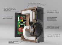
I found it remarkable that the new Radiant Acoustic Clarity 6.2 has some something where the magnet can rest against. You get a better view in their marketing video on YouTube. I attached a screenshot.
The marketing claim is to minimize distortion as much as possible (I guess at given price point).
They also use a sandwich of aluminum and MDF for the baffle but it looks like there is nothing in between.
The marketing claim is to minimize distortion as much as possible (I guess at given price point).
They also use a sandwich of aluminum and MDF for the baffle but it looks like there is nothing in between.
Attachments
Forgot to mention, air is an isolator. So mounting "dry" will always have some air in between, high impedance and "room" to move/vibrate. Mounting "wet" will allow energy to pass , low impedance.
Example ( early years): mounting a vibration sensor in a M16 bolt on rotating equipment dry would give different result ( more noises etc) versus mounted wet, same torque applied.
Example ( early years): mounting a vibration sensor in a M16 bolt on rotating equipment dry would give different result ( more noises etc) versus mounted wet, same torque applied.
Yes i use a magnet "support" for the midranges (Purifi ptt04M08-nac03) as well, with some putty like substance in between ( so no air layer entrapped in between). And a small support to support the magnet in vertical direction, so to offload the elastic washers used to mount the driver in the baffle (and also added some putty as well to provide some damping) .
The part not to be forgotten is the acoustic result. Resonances and vibration transmission only is of any importance if there is any noticeable.
Rule of thumb, any big panel wil couple more easily to surrounding air than small panels. And therefore will produce more acoustic output.
Rule of thumb, any big panel wil couple more easily to surrounding air than small panels. And therefore will produce more acoustic output.
Hi again.
The last two weeks I had very limited time to work on the speakers.
Following the felt placement and gluing the inner front panel we mounted the second layer of the enclosure; this is a layer of Finsa Compac Plus and will increase the mass and stability of the enclosure.
Where the original inner enclosure was easy to move by one person, it now becomes harder.
We glued this layer in a slightly larger size as these large panels tend to drift a bit, and the enclosure will be off half a millimeter here and there. Removing the oversize with a copier cutter is a fairly easy task.
The amount of clamps needed forced us to glue one speaker at the time (one per day, to ensure full drying of the glue)
.jpg")
.jpg")
.jpg")
Also the metal parts that we wanted to become black are powder coated. We investigated anodizing but it needed quite some snad-blasting or sanding so an oven baked powder coat was tested and we love the result.
.jpg")
.jpg")
.jpg")
.JPG")
That's it for today.
Cheers, Peter
The last two weeks I had very limited time to work on the speakers.
Following the felt placement and gluing the inner front panel we mounted the second layer of the enclosure; this is a layer of Finsa Compac Plus and will increase the mass and stability of the enclosure.
Where the original inner enclosure was easy to move by one person, it now becomes harder.
We glued this layer in a slightly larger size as these large panels tend to drift a bit, and the enclosure will be off half a millimeter here and there. Removing the oversize with a copier cutter is a fairly easy task.
The amount of clamps needed forced us to glue one speaker at the time (one per day, to ensure full drying of the glue)
Also the metal parts that we wanted to become black are powder coated. We investigated anodizing but it needed quite some snad-blasting or sanding so an oven baked powder coat was tested and we love the result.
That's it for today.
Cheers, Peter
Last edited:
Hi Jan,
This is inspired by Finite Elemente from Germany called Cerabase. You can buy these kind of pucks also at AliExpress but none had the right specs like the M10 bolt in the top with matching top (that I added to lock the M10 bolt when you adjust the height). And many are made from aluminium that I think is less ideal.
The concept is based on a stainless steel base and cylinder that rest on 3 ceramic (bearing) balls.
The function is very comparable to spikes and should prevent resonances to be transported into the floor due to the very small contact area. (like a spike)
The rubber grommets are just there so that the base does not slip off when moving but will have no negative effect of accidentally transporting energy to the base.
Hope this makes sense.
Peter
Hi Forum
The internal housing is finished

It is now waiting for the front and rear panel:
Work in Progres

the two mid range positions are under an angle of 3,3 degrees and ar furst cut on a 30axis to remove most of the material and the will move to a 5-axis.
That is why these holes look a bit strange.

It produces quite some curls

And these are the plate amps on a custom mounting, with stand-offs for maybe a shield


and view from the control/connect side

slowly moving in the right direction
The internal housing is finished
It is now waiting for the front and rear panel:
Work in Progres
the two mid range positions are under an angle of 3,3 degrees and ar furst cut on a 30axis to remove most of the material and the will move to a 5-axis.
That is why these holes look a bit strange.
It produces quite some curls
And these are the plate amps on a custom mounting, with stand-offs for maybe a shield
and view from the control/connect side
slowly moving in the right direction
Look´s superexpensive with the aluminium and the workprocess.
But your speakers going to look "like a miljon buck´s"
Hope your endresult become like "you wanted" 👍
But your speakers going to look "like a miljon buck´s"
Hope your endresult become like "you wanted" 👍
- Home
- Loudspeakers
- Multi-Way
- Building the best 3-way (NOT) full range speaker in the world