Hi Mikewxyz, we ordered 2 PCB's and payed around €170 each, I already did this before in my Tube based Phono Amplifier that you can find here: SRPP Phono
But I do not think this is going to be a commercial speaker. Joost and I build 2 sets. And in the process that started a exactly a year ago we made some decisions as you can read in this thread. The PCB that you see here was driven by the low cross-over frequency of around 150Hz and the very large and expensive Mundorf Film caps that we would need for the low impedance Mid-Range speakers (approximately 150µ and 300µ) to make a 4th order Linkwitz-Riley slope. doing this active would give us more tweaking options.
A production version of this project would retail in the order of 70k to 100k at least, where the shop would have a 100-120% markup in normal high end shops.
I have not calculated the real cost (spending it over the cause of a year makes it less painful) but I guess we are reaching €10k for the speakers with the walnut outer shell, the aluminium front and back, the custom feet, and of course the units. The BOM of the active filter reaches €2k.
And I did sell my original speakers quite well so I had a good starting budget. The new owner is also very happy with them as he would have spend 6 times more for a similar quality.
The active filter:
A fully balanced transformer coupled (and balanced electronics) with Spakos discrete op-amps, a discrete very low noise voltage regulator and with an adjustable slope of 6, 12, 18 and 24dB/octave and frequency setting between 150 and 500Hz this unit is quite universal and could be used with any of the hybrid designs out there including all DIY projects from Troels Gravesen that uses a Hypex for LF.
Maybe these active filters will come available in a year from now. If they sound as good as I hope they will, they will be replaced by a second generation that I am designing now. (it rains in the Caribbean, so I need to spend my holiday differently)
By adding a source input selection, 2 op-amps per channel and a full attenuation range volume control this can be come a full functioning pre-amp with build in cross-over and we can sell our pre-amp. The idea is that this will sound better than separates. Of course I will go the extra mile. Increase the power-supply and put that including control surface in a separate enclosure 🙂.
But that will become a seperate thread when it happens.
Cheers......

It lives.
With some very tiny modifications (actually only in the slow relay mute circuit) the unit is up and running.
As Jan Didden predicted that the super reg can oscillate with the AS797 opamp ..... it did.
I had some OPA627 metal cans laying around and they performed completely quiet.
I would like to investigate why this happens, but the OPA627 is not a bad opamp, so if it has to stay it will stay.
The noise figures of the unit look very promising
With a shorted input (AP generator in off) the unit shows -119dB residual noise (filtered with 22 to 22kHz)

A-weighted -122dB

and still almost -100dB unweighted

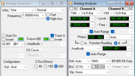
The test setup with The AP system 2.
Unfortunately I am home on holiday so I couldn't use the slightly better APx555B that we have in the office, but this is fine too

The finished board

This is the frequency response of the LF output (it has no filter, as that is done in the DSP of the Hypex) with the 15 1dB attenuation setting of the build in analog attenuator to match the gain of an LF with HF amp.
This output will be used with a downstream LPF of approximately 150Hz
The deviation in the high frequencies are due to the not damped Lundahl transformers that sound better this way.
Left and right are plotted over each other.

This is an FFT of the same LF output with the fundamental removed (output is 2V or +6dBV) what is about the maximum the hypex needs for full output
Left and right are plotted over each other.

THD+N vs input voltage in 100k and 600 Ohm, those sparkos have no problem driving a load.
With the input at 5V the output is +6dB (that is the gain) so 10V
Left and right are plotted over each other.

This is the FFT with fundamental removed of the High pass Filter set at 153Hz
Left and right are plotted over each other.
This is the unit set at a HPF cross over of 266Hz with the settings at 6db, 12db, 18,db and 24dB per octave (1st, 2nd, 3rd, and 4th order slope)
Left and right are plotted over each other.

These are the different filter setting that we can use.
The Mini DSP pointed us into the direction of 150Hz
The settings are 133Ha, 153Hz, 173hz, 205Hz, 230Hz and 266Hz
Left and right are plotted over each other.

That is it for now.
Some metal work and we can start listening
Cheers
With some very tiny modifications (actually only in the slow relay mute circuit) the unit is up and running.
As Jan Didden predicted that the super reg can oscillate with the AS797 opamp ..... it did.
I had some OPA627 metal cans laying around and they performed completely quiet.
I would like to investigate why this happens, but the OPA627 is not a bad opamp, so if it has to stay it will stay.
The noise figures of the unit look very promising
With a shorted input (AP generator in off) the unit shows -119dB residual noise (filtered with 22 to 22kHz)
A-weighted -122dB
and still almost -100dB unweighted
The test setup with The AP system 2.
Unfortunately I am home on holiday so I couldn't use the slightly better APx555B that we have in the office, but this is fine too
The finished board
This is the frequency response of the LF output (it has no filter, as that is done in the DSP of the Hypex) with the 15 1dB attenuation setting of the build in analog attenuator to match the gain of an LF with HF amp.
This output will be used with a downstream LPF of approximately 150Hz
The deviation in the high frequencies are due to the not damped Lundahl transformers that sound better this way.
Left and right are plotted over each other.
This is an FFT of the same LF output with the fundamental removed (output is 2V or +6dBV) what is about the maximum the hypex needs for full output
Left and right are plotted over each other.
THD+N vs input voltage in 100k and 600 Ohm, those sparkos have no problem driving a load.
With the input at 5V the output is +6dB (that is the gain) so 10V
Left and right are plotted over each other.
This is the FFT with fundamental removed of the High pass Filter set at 153Hz
Left and right are plotted over each other.
This is the unit set at a HPF cross over of 266Hz with the settings at 6db, 12db, 18,db and 24dB per octave (1st, 2nd, 3rd, and 4th order slope)
Left and right are plotted over each other.
These are the different filter setting that we can use.
The Mini DSP pointed us into the direction of 150Hz
The settings are 133Ha, 153Hz, 173hz, 205Hz, 230Hz and 266Hz
Left and right are plotted over each other.
That is it for now.
Some metal work and we can start listening
Cheers
Attachments

One plot fell off.
This is the FFT with fundamental removed of the High pass Filter set at 153Hz
Left and right are plotted over each other.

This is the FFT with fundamental removed of the High pass Filter set at 153Hz
Left and right are plotted over each other.
Hi Jan, you are most welcome. Hope to see you in a future AES NL section meeting.
Now you are here, and for learning purpose in this forum.
You predicted the AD797 to is oscillate. And it did (about a 20mV at 6GHz)
What can we do to prevent this as the opamp gives such great results in your supply.
Peter
Now you are here, and for learning purpose in this forum.
You predicted the AD797 to is oscillate. And it did (about a 20mV at 6GHz)
What can we do to prevent this as the opamp gives such great results in your supply.
Peter
And it works, and sounds awesome.
I need to make en extra XLR cable as the ones I have were to short, that is why the unit still sits on top of the rack, but will be placed underneath my Center Speaker.

It is like a veil is removed. everything sound so much better, also the LF sound better.
I can now start finalizing the the MF/HF passive filter that sits still outside my speaker.
The MiniDSP is a very good and flexible device but is the limitation for the last bit of resolution and cleanness. I think the ADC in the MiniDSP Flex HT is most likely the limiting factor but I am not sure.
So I decided to do some measurements on the MiniDSP and here are some results.

This is the most disturbing plot and I cannot explain this. THD+N vs output amplitude
The bottom 4 traces are my discrete analog filter (and the yellow spike, is a measuring error where the source settles to a new value with a relay), the top 4 are the from the Mini DSP
The MiniDSP is specified to 4V output and that is exactly where the unit clips. No problem in my setup where the amximum input voltage to the Hypex is around 2V for 500W output
But the high distortion at lower levels is strange. I measured with an A-weighting filter to remove out of band residue.

This is a very nice plot of a 1k signal at with the fundamental removed.
But the strange thing is that normally I get a dip at the fundamental (lower redtrace is the AP self) the Magenta is the MiniDSP
Very clean though

This is how I was using the Mini DSP.
LF 11dB louder than the MF/HF where the latter had a 4th order LR HPF at 153Hz.
Sure bandwidth is hard limited to 20k......
All the above says very little about the sound, but interesting to see the measurement differences.
But I am really really happy with the result so far. Best sound in my home to date.
Cheers,
Peter
I need to make en extra XLR cable as the ones I have were to short, that is why the unit still sits on top of the rack, but will be placed underneath my Center Speaker.
It is like a veil is removed. everything sound so much better, also the LF sound better.
I can now start finalizing the the MF/HF passive filter that sits still outside my speaker.
The MiniDSP is a very good and flexible device but is the limitation for the last bit of resolution and cleanness. I think the ADC in the MiniDSP Flex HT is most likely the limiting factor but I am not sure.
So I decided to do some measurements on the MiniDSP and here are some results.
This is the most disturbing plot and I cannot explain this. THD+N vs output amplitude
The bottom 4 traces are my discrete analog filter (and the yellow spike, is a measuring error where the source settles to a new value with a relay), the top 4 are the from the Mini DSP
The MiniDSP is specified to 4V output and that is exactly where the unit clips. No problem in my setup where the amximum input voltage to the Hypex is around 2V for 500W output
But the high distortion at lower levels is strange. I measured with an A-weighting filter to remove out of band residue.
This is a very nice plot of a 1k signal at with the fundamental removed.
But the strange thing is that normally I get a dip at the fundamental (lower redtrace is the AP self) the Magenta is the MiniDSP
Very clean though
This is how I was using the Mini DSP.
LF 11dB louder than the MF/HF where the latter had a 4th order LR HPF at 153Hz.
Sure bandwidth is hard limited to 20k......
All the above says very little about the sound, but interesting to see the measurement differences.
But I am really really happy with the result so far. Best sound in my home to date.
Cheers,
Peter
That just shows where the residual noise (the noise floor line) is coming from: before or after the fundamental notch filter.But the strange thing is that normally I get a dip at the fundamental (lower redtrace is the AP self) the Magenta is the MiniDSP
Nice! sure looks good too.And it works, and sounds awesome.
Would be hard to put the lid back on.
Something about Red and Black. It always just works visually.
The two aluminum strips running from front to back house the series transistors of the regulator and get fairly warm. With a heat pad it will be thermally connected to the top tha greatly reduces the temperature
I had not opened the MiniDSP Flex HT, but here is what's inside:
NE5532 op-amps for the RCA inputs and OPA1602 for the balanced inputs driving the ADC
This is an AKM AK5578. A decent unit.
The the DA stage is build around 4 (four) 8 channel ES9017 DACs, that is quite a combination.
This means that the unit uses 4 DACs in parallel per channel (or in set of 2 in pushpull) and they drive the outputs with OPA1612 op-amps.
Not bad at all.
- Home
- Loudspeakers
- Multi-Way
- Building the best 3-way (NOT) full range speaker in the world