This Error-Correction/Composite Combo amp is based on Mr Evil "Unnamed feedback method explored" and Nickolay Shvydky "My ZD-50 ultralow distortion chipamp"
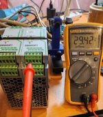
Output power at +/-29.5V: 8 ohms clip at 42W, 4 ohm clip at 65W. It is very stable in both EC and Comp mode. Ans it behaves very well after clipping.
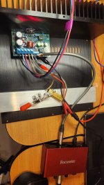
I could only measure its THD+N very roughly using Focusrite Solo 3rd, which has a minimal line-out and line-in THD+N of 0.002%.
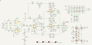
U1 is OPA1655 and U2 is OPA828. For error-correction(EC) mode, RV1 was set at 330ohm. For composite (Comp) mode, RV1 was set at 680 ohms.
Final Remarks
Today marks the completion of my 6xLM3886 PBTL (Parallel Bridge-Tied Load) amplifier, now fully assembled and installed in its case. Hearing music flow from the amp for the first time was an incredibly rewarding moment.
This has been the most time- and resource-intensive DIY amplifier project I've undertaken. It all began with a spark of curiosity after discovering HAYK’s thread, which then led me to explore designs by Nickolay Shvydky (ZD-50), Mr. Evil’s EC-correction, and Tom’s Modulus series.
I initially started with the ZD-50, but its complex compensation network proved daunting. I decided to pursue a simplified approach. After many hours with LTSpice, I developed a streamlined version of the design, which is shared below.
The first prototype used through-hole components and served as both a learning and testing platform. Getting the amplifier stable took significant effort, with a variety of issues encountered and resolved along the way.
Next came the 2xLM3886 parallel version, which helped me better understand the parallel operation of the LM3886. It also served as a base for further schematic refinement and testing.
Throughout development, I upgraded my test equipment for greater precision, allowing for more accurate measurements and analysis.
The final goal was this 6xLM3886 PBTL amplifier. With the knowledge gained from the earlier versions, I was able to optimize the circuit design, select key component values carefully, and fine-tune the PCB layout. The result is a high-performance amplifier with impressive specifications:
(Note: These measurements were taken using amateur-grade equipment under informal conditions. They are provided for reference only and should not be interpreted as certified or industry-standard specifications.)
I’ll now spend some time listening to the amplifier and enjoying the results. Meanwhile, I plan to revisit the earlier versions and design optimized PCBs for them as well.
(I made 5 sets PCB, minimal number of ordered sets, of the amp, there are 1 sets left for sale, see swap meat)
2xLM3886 EC/Comp
+/-32V 80W 4ohm, THD+N<0.0006%, Noise 10uV.
Output power at +/-29.5V: 8 ohms clip at 42W, 4 ohm clip at 65W. It is very stable in both EC and Comp mode. Ans it behaves very well after clipping.
I could only measure its THD+N very roughly using Focusrite Solo 3rd, which has a minimal line-out and line-in THD+N of 0.002%.
U1 is OPA1655 and U2 is OPA828. For error-correction(EC) mode, RV1 was set at 330ohm. For composite (Comp) mode, RV1 was set at 680 ohms.
Final Remarks
Today marks the completion of my 6xLM3886 PBTL (Parallel Bridge-Tied Load) amplifier, now fully assembled and installed in its case. Hearing music flow from the amp for the first time was an incredibly rewarding moment.
This has been the most time- and resource-intensive DIY amplifier project I've undertaken. It all began with a spark of curiosity after discovering HAYK’s thread, which then led me to explore designs by Nickolay Shvydky (ZD-50), Mr. Evil’s EC-correction, and Tom’s Modulus series.
I initially started with the ZD-50, but its complex compensation network proved daunting. I decided to pursue a simplified approach. After many hours with LTSpice, I developed a streamlined version of the design, which is shared below.
The first prototype used through-hole components and served as both a learning and testing platform. Getting the amplifier stable took significant effort, with a variety of issues encountered and resolved along the way.
Next came the 2xLM3886 parallel version, which helped me better understand the parallel operation of the LM3886. It also served as a base for further schematic refinement and testing.
Throughout development, I upgraded my test equipment for greater precision, allowing for more accurate measurements and analysis.
The final goal was this 6xLM3886 PBTL amplifier. With the knowledge gained from the earlier versions, I was able to optimize the circuit design, select key component values carefully, and fine-tune the PCB layout. The result is a high-performance amplifier with impressive specifications:
- Power Supply: Hammond 1182T24 625VA transformer (24VAC/13A dual secondary), DIYAudio Store Universal Power Supply board, and 140,000µF of filter capacitance
- Output Power:
- 175 W into 8 ohms @ THD+N 0.00023%
- 240 W into 4 ohms @ THD+N 0.00042%
- Residual hum/noise floor: ~10 µV
(Note: These measurements were taken using amateur-grade equipment under informal conditions. They are provided for reference only and should not be interpreted as certified or industry-standard specifications.)
I’ll now spend some time listening to the amplifier and enjoying the results. Meanwhile, I plan to revisit the earlier versions and design optimized PCBs for them as well.
(I made 5 sets PCB, minimal number of ordered sets, of the amp, there are 1 sets left for sale, see swap meat)
2xLM3886 EC/Comp
+/-32V 80W 4ohm, THD+N<0.0006%, Noise 10uV.
Attachments

Last edited:

At beginning of the design and testing, there were oscillation all over the place. It also was met with oscillation after clipping.
From left to right: 3.5Mhz 500mV oscillation, clipping at output 18.75Vrms, oscillation after clipping, oscillation after reduced input signal, oscillation with no input signal.
But thru few days intensive testing and adjustment of the compensation capacitors, it has been finally successful.
From left to right: 3.5Mhz 500mV oscillation, clipping at output 18.75Vrms, oscillation after clipping, oscillation after reduced input signal, oscillation with no input signal.
But thru few days intensive testing and adjustment of the compensation capacitors, it has been finally successful.
Attachments
-
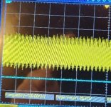 Fig74 small input after oscillation2.jpg57.1 KB · Views: 373
 -
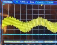 Fig73 small input after oscillation1.jpg78.8 KB · Views: 250
 -
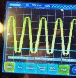 Fig72 LM3886 clip oscillation 3_5Mhz 500mvPP.jpg52.6 KB · Views: 228
 -
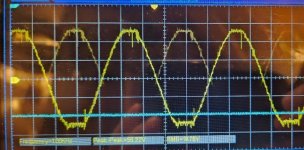 Fig71 LM3886 clip.jpg108.2 KB · Views: 225
 -
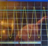 Fig58_2 3_5MHz 500mV.jpg39.7 KB · Views: 379
 -
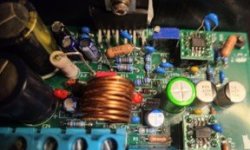 Fig98 EC LM3886.jpg17.3 KB · Views: 386
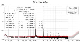
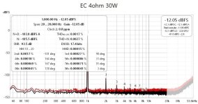
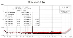
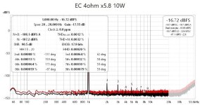
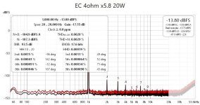
THD+N on benchtop. It was open, with high testing components rising high.
My measurements are 10-20X worse (20db) than TI spec and Modulus-86 Spec. That's the problem of my measurement setting up.

My measurements are 10-20X worse (20db) than TI spec and Modulus-86 Spec. That's the problem of my measurement setting up.
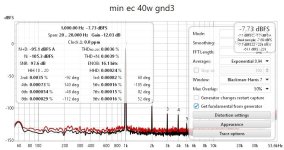
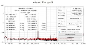
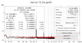
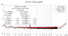
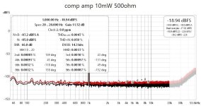
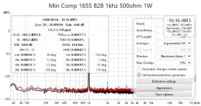


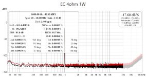
EC mode low gain 5.8X. Since Focusrite Solo can only have 2.4Vrms output, so high output power was not measured. It was done by put a 49.9K resistor parallel to 21.2+21.2K resistors in FB loop (in both brunches).
Attachments
Last edited:
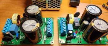
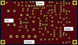
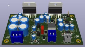
PCB layout
Top: GND, Output
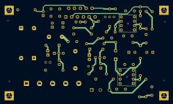
Inner 1: signal
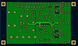
Inner 2: negative -30V/-15V
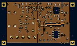
Bottom: +30V/15V
Top: GND, Output
Inner 1: signal
Inner 2: negative -30V/-15V
Bottom: +30V/15V
Attachments


I am waiting for the power supply case, and doing some mechanical work on the amp case.
I will listen Modulus-86 10th Edition and my EC amp later on.
A parallel LM3886 EC-Comp amp is in design phase. It is being finalized and will be published soon. It can be configured into EC or Comp amp by 2 jumpers. And it can also be configured to an inverter or non-inverter amp by another jumper as well.
Attachments
Last edited:
I was always interested in Penasa's Evo with double current pump so I'm looking forward to your parallel solution.
Focusrite is quite decent for it's money, I think that EMU 1212m or Lynx L22 will be a bit better but need PCI or EMU 0404 for USB. You are on tough position 'cause both ZD-50 and Modulus have very low distortion figures and test machines that good cost an arm and a leg.
Focusrite is quite decent for it's money, I think that EMU 1212m or Lynx L22 will be a bit better but need PCI or EMU 0404 for USB. You are on tough position 'cause both ZD-50 and Modulus have very low distortion figures and test machines that good cost an arm and a leg.
I hope I'm not throwing down the gauntlet by saying this, but I wonder how this will compare to a similar product by Neurochrome?
He says that his amp will not oscillate even with a 2.2 uF cap in parallel with the load.
I have 4 of his amps and they are excellent.
Of course, I am always excited to see newcomers and their take on a similar problem. Will this be a commercial product for sale or a diy thing? Can we expect to buy some boards one day soon or is it simply a personal project?
https://audioxpress.com/article/r-d-stories-the-neurochrome-story
It is a project which anyone can try/diy it. No commercial interests here.
The single LM3886 version was tested with excellent stability.
But I have no means to measure its true THD+N.
The single LM3886 version was tested with excellent stability.
But I have no means to measure its true THD+N.
What does that mean?The single LM3886 version was tested with excellent stability.
Did you look at the step response with increasing capacitance across the load? How about clipping behaviour with a sine wave input?
Tom
With the value in the schematics, the clipping behavior is excellent. I can increase the input to bring the amp to clip, then reducing the input bring it back to normal. No oscillation.
I haven't done the capacitor load test yet. I will try it shortly.
I haven't done the capacitor load test yet. I will try it shortly.
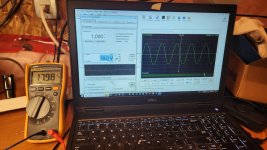
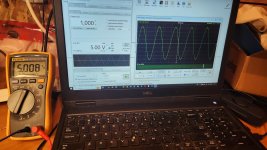
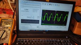
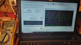
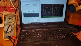
Clipping clipping behavior: PW +/-29.5V, 8Ohm resistor, 1Khz sine wave.
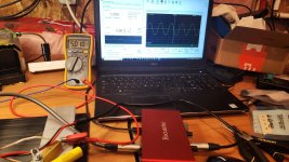
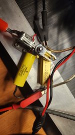
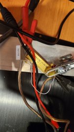
1. setup
2. 5Vrms output
3. 18Vrms output, clean clipping
4. reducing input back to 5Vrms output
5. hard but clean 20Vrms clipping
1. setup
2. 5Vrms output
3. 18Vrms output, clean clipping
4. reducing input back to 5Vrms output
5. hard but clean 20Vrms clipping
Attachments


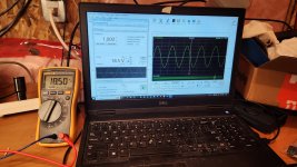
capacitance load and clipping behavior at small capacitor load: PW +/-29.5V, 8Ohm resistor//0.47uF capacitor, 1Khz sine wave.
1. setup
2. 5Vrms output
3. setup
4. 16Vrms output
5. 18.5Vrms output, looks like with a small capacitor, clipping at higher output voltage
6. 19Vrms output, the amp clips and lost stability.
But by reducing the input, the amp becomes stable again.
1. setup
2. 5Vrms output
3. setup
4. 16Vrms output
5. 18.5Vrms output, looks like with a small capacitor, clipping at higher output voltage
6. 19Vrms output, the amp clips and lost stability.
But by reducing the input, the amp becomes stable again.
Attachments
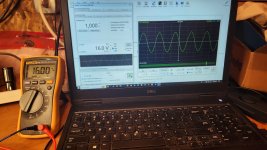
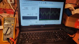
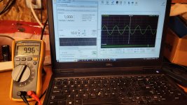
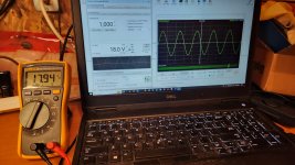
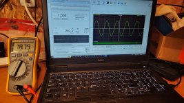
capacitance load and clipping behavior with large capacitor: PW +/-29.5V, 8Ohm resistor//2.2uF capacitor, 1Khz sine wave.
1. setup
2. 5Vrms output
3. 10Vrms output
4. 18Vrms output
5. 19Vrms output, it starts clipping but stable
6. 20Vrms output, the amp clips but stable
1. setup
2. 5Vrms output
3. 10Vrms output
4. 18Vrms output
5. 19Vrms output, it starts clipping but stable
6. 20Vrms output, the amp clips but stable
Attachments
- Home
- Amplifiers
- Chip Amps
- A New EC-Composite LM3886 Amp