You probably won't notice the shortcomings as long as you don't try to reproduce realistic music levels on inefficient 4-ohm speakers.I listen (at the moment) to classical music with the current MF-A1 model. And I have nothing to complain about.
Ed
You probably won't notice the shortcomings as long as you don't try to reproduce realistic music levels on inefficient 4-ohm speakers.
Ed
As the owner of an original A1, one have to know this, I know all this. Up to 5W at |Z| > 6 Ohm everything is fine. But this is not about my A1 (the MF original), but about all kinds of offshoots - better or worse ones.
HBt.
Psst
We should point out the weaknesses and also the why. Of course also strengths, if the design has any?! My only concern here /the topic is the circuit design.
The strength is that it is a class A amplifier. It has zero crossover distortion.
The weakness is that the gain and output current drive are both low. As a result of low gain, distortion is high. The output has significant hum as Stereophile measured.
All of that can be improved with higher gain and a real output stage, without giving up class A operation. I am not sure why class A amplifier designs are often so limited, when it is easy to design class A amplifiers that will outperform class AB amplifiers (*).
Ed
(*) Except for power output.

You can increase the open loop gain by replacing the 2.2k resistors with current sources. You could go a step further by inserting a cascode in there to increase the output impedance of the input transistor(s). But now it's getting a lot "busier", circuit-wise.
You might want to take a look at the old JLH HA (the symmetrical design). It uses an auto-bias scheme for the output transistors, but it also makes for a dandy "auto-biasing" CCS for the input transistors as well.....in my experience, anyway.
You might want to take a look at the old JLH HA (the symmetrical design). It uses an auto-bias scheme for the output transistors, but it also makes for a dandy "auto-biasing" CCS for the input transistors as well.....in my experience, anyway.
Let's stick with the schematic from post #1 for a moment before we design an even better A1 than the original already is. Maybe we can actually replace Zen-Mod's combination of the IRFxxxx and the TTAxxxx with the Toshiba IGBT?
#
What do we actually think of this type of quasi-quiescent current control?
#
What do we actually think of this type of quasi-quiescent current control?
This is the actual core of the A1, Tim de Paravincini's idea - unfortunately it is not yet ready for practical use - but that's it!

It is possible (but this cannot be ruled out) that "Master Tim" has now noticed, or knew in advance of the experiment on his kitchen table:
"this is not how it works, I need a set of impedance converters, simple emitter followers."

"this is not how it works, I need a set of impedance converters, simple emitter followers."
The schematic on post 1 wont work as the biaising voltages are completely out but even if polarized accordingly
it wont be any good for audio, eventualy to drive an electrical motor.
Anyway all those amps with controled current OSs have always been a recipe for disaster, miserable perfs and often
poor behaviour, it s not by chance that they were not adopted by all serious brands, they only found their way
in some PA systems, QSC FI, and cheap guitar amps.
Last edited:
Let's quickly continue with the chronology:
"Master Tim" ensures a good portion of asymmetry in the differential pair and sets an offset voltage (which, incidentally, can no longer be prevented, so it somehow results anyway).

"Master Tim" ensures a good portion of asymmetry in the differential pair and sets an offset voltage (which, incidentally, can no longer be prevented, so it somehow results anyway).
The schematic on post 1 wont work as the biaising voltages are completely out but even if polarized accordingly
it wont be any good for audio, eventualy to drive an electrical motor.
I would never even use them as motor drivers, although I have used a similar concept for a disk rotor before.
This is absolutely true, this type is not necessarily safe to operate.Anyway all those amps with controled current OSs have always been a recipe for disaster, miserable perfs and often
poor behaviour,
Thank goodness - the MF-A1 remains an explosive exotic audio amplifier!it s not by chance that they were not adopted by all serious brands,
I didn't know that yet.they only found their way
in some PA systems, QSC FI, and cheap guitar amps.
@wahab
Don't we want to help the "Zen master" a little?
greetings,
HBt.
🙂
Q3 and Q4 are not controllable without a real, powerful driver ---> a Darlington would be it, but right from the start with a real Darlington you generate completely different problems ...

#
Well,
what should the RC link R11 & C3 do?
#
Well,
what should the RC link R11 & C3 do?
Slowly, the step-by-step sketch (intended as a thought support) approaches the original MF-A1 schematic.
In terms of DC voltage, everything is now paletti, and if one half is the exact mirror image of the other half (bad SE amps), a quiescent current (through the self-conducting output stage) of approx. 800mAdc flows.
However, an AC input voltage cannot really be amplified yet, the apparently separate AC feedback loops are missing.

Will this litter /throw ever be a good one?
In terms of DC voltage, everything is now paletti, and if one half is the exact mirror image of the other half (bad SE amps), a quiescent current (through the self-conducting output stage) of approx. 800mAdc flows.
However, an AC input voltage cannot really be amplified yet, the apparently separate AC feedback loops are missing.
Will this litter /throw ever be a good one?
I am new to this circuit. At first glance, as the NFB point is not at the output point, when it runs over class A region, the performance will suffer.
The gimmick of the "master's idea" is also one of the biggest weaknesses of the design.
Considered as a single-ended circuit, one could assume a true class A setting up to a maximum of 2.5Wrms.Is the original design Class A or Class AB?
But take a very deep look at the control loop.
#
The intention of the thread is to promote understanding of this strange circuit and at the same time ask if @Zen Mod circuit (from posting #1) is really an improvement. If it does, why and in what ways?!
HBt.
Now we should get down to the nitty gritty / back to business
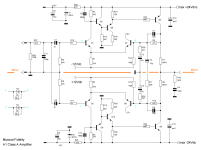
Attached you will find the last picture of the circuit diagram for the time being.
Let the relentless analysis (and simulations) begin.
Beginners would certainly like to know exactly how this (now somehow ingenious) amplifier works and whether it can be improved at all (and how).
At the same time, there is a discrepancy in the official specification of the damping factor of 150; a typing error?, 15.0 ?!
HBt.audio
Attachments
At least the JLH approach has some emitter-degen resistors on the output transistors. Their absence in the MF-A1 strikes me as a poor design choice. I'd worry about thermal runaway.
Setting the idle current also looks problematic to me. The only way(s) to accomplish it rely on adjusting (or selecting) pairs of resistors in the top & bottom circuit blocks. This also can affect the output offset because the currents in the output transistors have to match. And adjusting the tail currents will affect the Gm of the diff pairs, along with the bias current. The latter issue probably would only have a minor impact on circuit performance but I'd know it's there.....
Personally I'd pass on building this one.
Freie Ton-u. Bildwerkstatt
The heroes and many a seer cavort in the vastness of the iUniverse; so what about the seemingly messed-up kitchen table design, which actually wants to be a tube amplifier, and with which the MF company manifested its success?
What does a repair man from my country write about this?
Disclaimer
I am passing on Mr. Kühne's thoughts here without any evaluation.
Attachments
- Home
- Amplifiers
- Solid State
- An A1 descendant - a relentless analysis