The ATC mid dome guide looks very simple. Looks like the profile of the quarter round bit I'm using. Probably 3/4" radius or thereabouts.think you cold mimic atc mid wave guide profile ? or the dome is too small
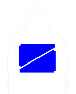
The trick to making it is to cut a perfectly round hole of the desired diameter (dome + a few mm more), then use a quarter round bit with a guide bearing against the inner wall of the hole you made to cut the contour. I used a 80mm hole saw bit (or blade or whatever you want to call it) on a drill press to cut the 18mm BB plywood AND the same hole in another 10mm board. Because the bearing guide has to ride below the depth of the radius, the hole has to be deeper.
Not sure if that last portion makes sense. If you are a wood router user, it will makes sense.
But to answer your question, yes I could replicate that wave guide.
The one I made first had a quarter-round shape like this --
But then I sanded the top portion of the "exit" hole so that it ended something more like this -- a longer contour curving more gradually to the baffle plane. Not like the wood with ledge shown but the second outline.
Because of the risk of damaging the 68mm beryllium dome during mounting, I would not make the starting hole any smaller than 73~75mm. I suppose if you could shape the backside of the waveguide with a template that provides a safe secure guide to mount the waveguide to the dome faceplate, you could get closer to 68mm. Not sure if any gain from that is worth the time & effort. CNC would make it easier. Or 3D printing -- but for this project, I want a smooth, all-BB front baffle, no plastic.

Mine are approximately 295Hz, ~31 Ohms max. These are an early, mid-70’s pair and were used daily, which may have kept the suspension soft. I can post a measurement later if it’s beneficial.Perhaps other NS1000 or JA0801 owners here can be persuaded to measure theirs?
Last edited:
after 7 mo I finally ordered the parts. The wait enabled me to make a 0.6mm plate that I'll test out on the back of the ja0801 (the plate size did not exist 7mo ago). It could be a flop... only one way to find out.
The monotile will be 1.9mm thick stainless steel.
The monotile will be 1.9mm thick stainless steel.
Attachments

Baffle sim is done with an rough ideal driver sim. Looks like an lr12 is ideal.

It will be a week before the baffle parts ship. I noticed Troels used a LR4 a bit higher than me. I do remember liking the t25b being -6db at 2200hz.
More to come. Next up should be a DATS test to see if the plate does anything and some other real measurements. I have two dayton mics to use.
It will be a week before the baffle parts ship. I noticed Troels used a LR4 a bit higher than me. I do remember liking the t25b being -6db at 2200hz.
More to come. Next up should be a DATS test to see if the plate does anything and some other real measurements. I have two dayton mics to use.
Attachments


Waiting for the loctite power grab to sit for 24 hours. I did an pretty good job at estimating the ja0801. I am a little bit off in the corners- like 1-2mm. It looks crazy with the stainless baffle.
In a little bit I'll see what the tiny plate does behind the yammy.
Last edited:


Amazing effort. Fabrications are really beyond me. I may have missed this but where are you planning to cross to the L26ROY? I was somewhat surprised to see it used by this company with the D7608 https://www.elfton.cz/?p=65, which probably can't go as low as the Yamaha.
Thanks, @motokok !Amazing effort. Fabrications are really beyond me. I may have missed this but where are you planning to cross to the L26ROY? I was somewhat surprised to see it used by this company with the D7608 https://www.elfton.cz/?p=65, which probably can't go as low as the Yamaha.
I am am spitball guessing the XO will be around 500hz. Troels used a LR4 at 500hz. http://www.troelsgravesen.dk/Yamaha-NS1000.htm
My l26roy does make a little mess around 300hz. I will make an "ideal driver" sim using simulated baffles and measurements to see what it suggest and then take real measurements with 2 mics.
That elton is over $8000. Crazy!
I do think the bass driver and tweeter I am using are better than what came with the original yammy box.
...
The baffle is mostly glued up. The only thing left to glue are the rear stands. I also need to put in some metal braces to hold it to my bass box.


I got the baffle all put together, hooked up the amps, played some music:
Glad the hypex amps did something to protect the driver but WFT I tested this driver when I got it? I once purchased a driver off ebay and it did the same thing: as the volume went up the fault protection would go off more.
After watching a video on how to clean the drivers:
I took the JA0801 apart and was hoping to see a messed up voice coil.


The coil looked fine?!?! The cleaning video gave me the idea of cleaning the magnet. So I stuck some tape in and there were some small chunks of something in there. The coil must have rubbed up against it because it all worked after cleaning.

Tape was used to grab anything stuck in the gap.
I did learn that the holes between JA0801 are not quite aligned the same. So each baffle is made for each driver once the holes are drilled.

I might make a felt layer the goes on top of the baffle but wont decide until a test on a smaller baffle. The stainless is a fingerprint magnet.
More to come!
These are readily available from Japan on Ebay. For those in not in the EU they can be had for half the price through Yahoo-auctions japan for half the price (most Ebay offerings are sellers buying from yahoo if you purchase on Ebay)
Have purchased 2 sets my self recently for a project.
Have purchased 2 sets my self recently for a project.
Thanks. I got lucky for sure. (I miss being able to listen to your room!)Nice recovery repair of that rare Yamaha driver...
I got mine on ebay. Thanks for the tip! Good luck with your project. What tweeter and woofer are you using?Have purchased 2 sets my self recently for a project.
......
Ok, I have a rough XO for an ideal sim:
This xo is based on nothing more than the SD and baffle so reality be different.
Now some real measurements:
Reality vs sim for the ja0801:

The above shows a sim polar vs an on and off axis measurement with a 5ms gate. The sim=dots, real=solid.
I am not as experience as many of the designers here but I think this is odd. As the gate goes up, it seems more flat:


The t25b and ja0801 both calibrated separately. There was a 1db difference between them. The t25b was louder.

I never expected this to be a design that is shooting for a flat response. My main interest is a chaotic decay. It seems to be doing that so far. EQ'ing will be interesting.
Last edited:
Sill measuring and digging into measurements.
The decay was something that interested me about the shape. The foam baffle had this decay at 1meter on axis:

The new baffle has this decay at 1m on and 40 degrees (or so) off axis:


It is a 500hz on up sweep.
The t25b at 1m on and off axis:


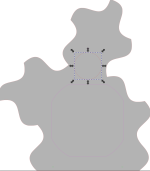
Also, a shot of the back of the baffle:

So far so good. I am listening to the sim xo with some tweaks and like it.
The decay was something that interested me about the shape. The foam baffle had this decay at 1meter on axis:
The new baffle has this decay at 1m on and 40 degrees (or so) off axis:
It is a 500hz on up sweep.
The t25b at 1m on and off axis:
Also, a shot of the back of the baffle:
So far so good. I am listening to the sim xo with some tweaks and like it.
Chipping away. I went to delusional route first: trying the sim XO.
It looked ok but I need to review the timings on the XO. Right now there is no delay on the ja0801 and there should be to match the L26ROY. This might account for the odd GD.
All measurements were taken at 1m and between the mid and tweeter.

Bass needed a boost. I will need to do things the right way to get a better look.

The decay looks pretty good. My previous designs all had some mess in the decay. This looks pretty good.

By hook or by crook I'll get this done...
It looked ok but I need to review the timings on the XO. Right now there is no delay on the ja0801 and there should be to match the L26ROY. This might account for the odd GD.
All measurements were taken at 1m and between the mid and tweeter.
Bass needed a boost. I will need to do things the right way to get a better look.
The decay looks pretty good. My previous designs all had some mess in the decay. This looks pretty good.
By hook or by crook I'll get this done...
Seems like the major issue still is directivity widening 2-3kHz in hor. plane. It influences decay too, most prominently in a room at listening listance (instead of anechoic chamber).
Have you measured or simulated vertical off-axis behaviour? Does vertical off-axis spl have a dip where hor has boost?
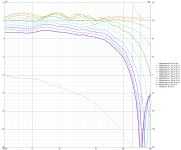
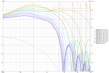
Edge sim of asymmetric baffle off-axis in four directions below. VCAD2 can sim multi-driver directivity too, but it takes more time to do...

Have you measured or simulated vertical off-axis behaviour? Does vertical off-axis spl have a dip where hor has boost?
Edge sim of asymmetric baffle off-axis in four directions below. VCAD2 can sim multi-driver directivity too, but it takes more time to do...
I got mine on ebay. Thanks for the tip! Good luck with your project. What tweeter and woofer are you using?
Thanks,
I have a set of T34B's for tweeters, want Purifi woofers, and the ting have kinda grown a bit expensive, so I have to save up some free money before it proceeds.
Tommy
Seems like the major issue still is directivity widening 2-3kHz in hor. plane. It influences decay too, most prominently in a room at listening listance (instead of anechoic chamber).
Have you measured or simulated vertical off-axis behaviour? Does vertical off-axis spl have a dip where hor has boost?
Edge sim of asymmetric baffle off-axis in four directions below. VCAD2 can sim multi-driver directivity too, but it takes more time to do...
View attachment 1370808
Hey! There is some extra power in the decay for the range but it is not ringing like my smaller rectangular speaker. (although the issue was baffle + pushing a driver lower than it wanted to go).
The vert sim has a dip. I actually wanted a dip. But the phase plug on the JA-0801 is the monkey wrench.

vert sim
I did a quick vertical series of measurements. They starts at the mid and move up the baffle at 1m. The last measurement is just past the baffle.


The noise floor is around 30db. It looks fairly random to my eyes. My ears don't find it sibilant in any way. If this was my other design, the ringing would show up in more than one measurement.
...


I did some alignment of the bass to the mid. It liked 320u.
Last edited:
I was actually looking at your system response of post#52, hor. widenig there. I xo is there, typically vertical off-axis dips at xo because of interference of M and D sources. Xo order affects this very much, eg. acoustic LR2 smooths out M/T vert. directivity dip compared to LR4 because T's minimal directivity compensates.
I am happy the LR12 was what stood out from the ideal driver sim. The reality looks better than what was predicted. I do have some eq on it though.I was actually looking at your system response of post#52, hor. widenig there. I xo is there, typically vertical off-axis dips at xo because of interference of M and D sources. Xo order affects this very much, eg. acoustic LR2 smooths out M/T vert. directivity dip compared to LR4 because T's minimal directivity compensates.
Determining when a LR12 is at its best spot seems to be another matter. I will need to balance the on-axis and off-axis to determine if I am using enough delay. Listen to music and flipping between settings is also something to try. I wish an LR12 w as as easy as an LR4 where you can invert and look for the lowest dip.

Flipping polarity with LR2 works as well, but naturally dip is not so sharp. Just remember that with LR2 the right polarity is opposed! I like to check step response too when fine tuning delays.
Steps of a 4-way speaker with LR2 vs LR4

Steps of a 4-way speaker with LR2 vs LR4
- Home
- Loudspeakers
- Multi-Way
- project: Emperor L26ROY (tweeter + Yamaha JA-0801 + Seas L26ROY)